EasyManuals Logo
Home>Veeder-Root>Measuring Instruments>TLS-350R PLUS

Veeder-Root TLS-350R PLUS Installation Manual

Veeder-Root TLS-350R PLUS
59 pages
To Next Page IconTo Next Page
To Previous Page IconTo Previous Page
Page #47 background imageLoading...
Page #47 background image
Appendix C: Device DIP Switch Settings Transmitter/Receiver/Repeater DIP Switch Settings
C-2
Transmitter/Receiver/Repeater DIP Switch Settings
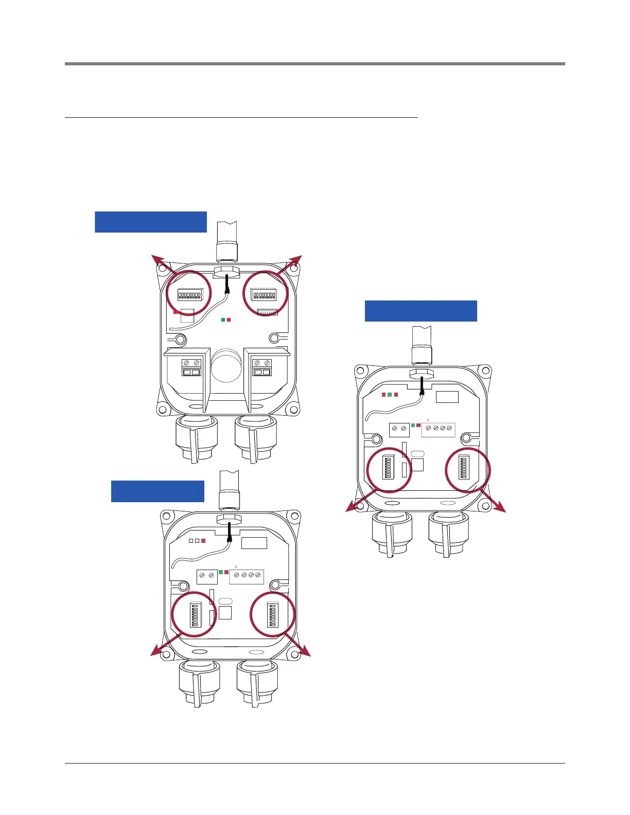
DIP switch locations for the Transmitter, Receiver and Repeater are shown in Figure C-2. Device DIP switch
settings for these devices are listed in Figure C-3 through Figure C-6 (use the appropriate settings for your
software version 1 or 3).
Figure C-2. DIP switch settings
S1
S1
S2
S2
S1
S2
TRANSMITTER
REPEATER
RECEIVER
c-2.eps
S1
S2
PWR
GND
+IN
-IN
BATTERY
PROBE
REPEATER
J4
S2
S1
J3
RS-485
GND
+15V
+15v
+
GND
TRANSMIT
RECEIVE
PWR
REPEATER
J4
S2
S1
J3
RS-485
GND
+15V
+15v
+
GND
TRANSMIT
RECEIVE
PWR

Other manuals for Veeder-Root TLS-350R PLUS

Questions and Answers:

Question and Answer IconNeed help?

Do you have a question about the Veeder-Root TLS-350R PLUS and is the answer not in the manual?

Veeder-Root TLS-350R PLUS Specifications

General IconGeneral
BrandVeeder-Root
ModelTLS-350R PLUS
CategoryMeasuring Instruments
LanguageEnglish

Related product manuals