HB-3plus Headset Adaptor Box 3
2.2.3 Desk Microphone Connection
The HB-3PLUS is designed to operate with Vega’s standard MD-MS desk microphone (electret)
or a dynamic desk microphone, for dispatch activities using Vega’s C-Soft dispatch software.
SELECT and UNSELECT audio is routed directly to the computer speakers. Internal jumper
JMP2 selects the electret or dynamic microphone configuration.
A – Electret
B – Dynamic
2.2.4 Headset ON/OFF switch
The headset ON/OFF switch is used to provide hook signaling to a Vega dispatch console or C-
Soft application. When OFF, SELECT audio switches from the headset to the speaker. When
using a desk microphone the switch must be in the OFF position.
2.3 Rear Panel Connections
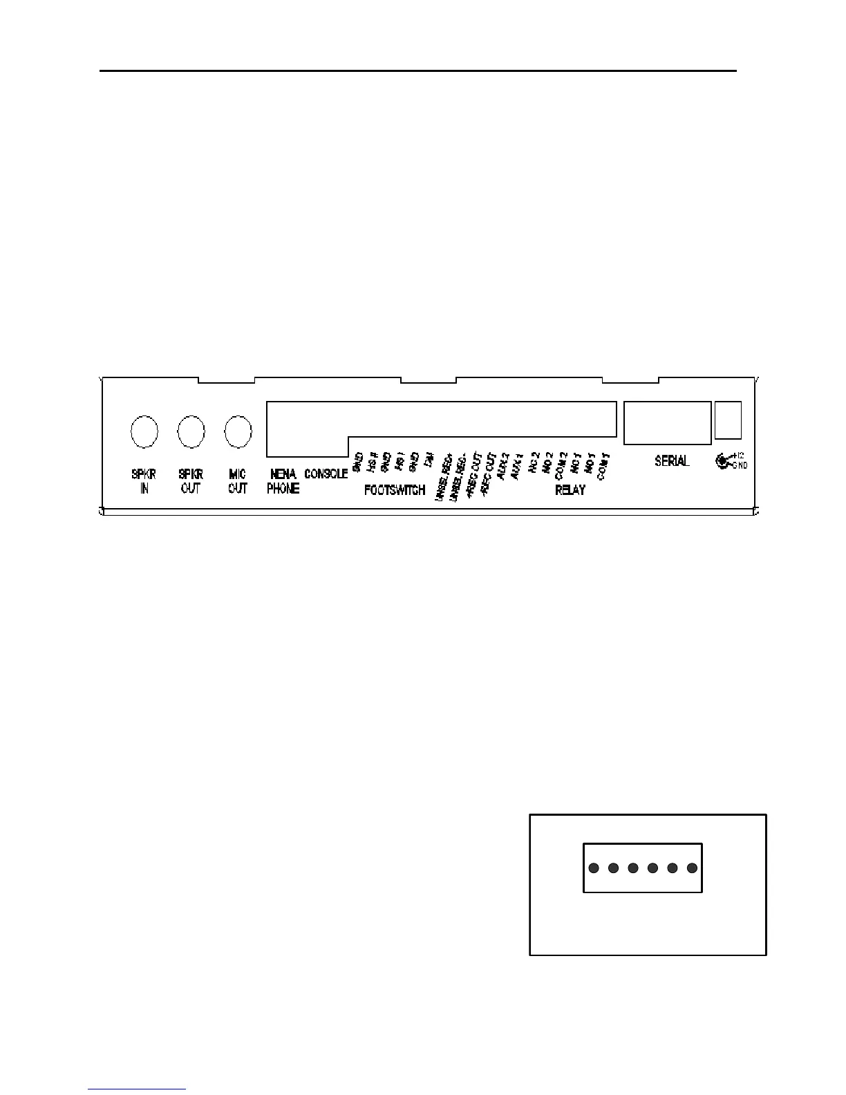
Figure 2 HB-3PLUS Rear View
2.3.1 Power Supply Connection
The HB-3PLUS power requirements are 12 to 16 VDC, 500mA. A wall mounted power supply is
included with the HB-3PLUS. Power connection is made via a 2.5mm plug receptacle on the rear
panel of the unit. The positive terminal is the center conductor.
2.3.2 Serial Connection
The serial port is enabled in the HB-3PLUS when the PC Mode is set by JMP8. The serial port is
configured for 9600-baud, 1stop bit, no parity, and DCE connections. A serial cable is provided
for connection to the PC.
In the PC Mode, the HB-3PLUS provides the PC with serial data for PTT, Monitor, relay control
and AUX input functions.
2.3.3 Relay Connections
The HB-3PLUS provides two Form C relay contacts for
general use. Each relay is controlled by the C-Soft
application; please refer to the C-Soft manual for use of this
feature. A 1 Amp resettable fuse protects both sets of
contacts.
A 6-pin screw terminal block provides connection to the
relays. Refer to Figure 3 Relay Connections drawing.
NOTE: The Relays Are Operational In The PC Mode ONLY
Figure 3 Relay Connections
1 2 3 4 5 6
1) Relay 1 COM 2) Relay 1 N.O.
3) Relay 1 N.C. 4) Relay 2 COM
5) Relay 2 N.O. 6) Relay 2 N.C.


 To Next Page