Note2
Note:Function description in brackets is
factory default
Analog monitoring
signal output
TA
TB
TC
+24V
Y
Shielded cable (the
end close to VFD
grounding)
_
mA
20
10
0
-
+
V
W
U
P
~
Shielded cable or armoured cable
(the end close to VFD grounding)
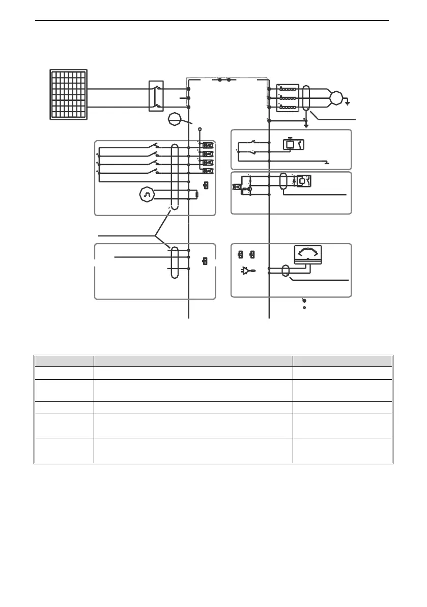
E
(The grounding resistance
is less than 10 ohms)
W
V
U
Output Rector
+10V
Frequency control input
GND
AI
Shielded cable (the end close to
VFD grounding)
Multi function contact input
(Water full detection reset)
(Water full detection alarm)
(Reverse)
(Forward)
GND
X3
X4
X1
X2
PB
Solar pump VFD
S
T
R
GND
A0
Coil
COM
Passive contact
output
AC220V
AC0V
Coil
MAX Output Of Contact:
3A/240VAC
5A/30VDC
1.MAX Output of +24V Port:DC24V/100mA
Note:When output type of AO port as
frequency and Voltage,
Maximum Output:2mA
2.Inner resistance of AI1/AI2 Port:100kΩ
1.MAX Output of +10V port :50mA
Note:
2.Max Output of Y Port :DC24V/50mA
Note:
represent control circuit terminals.
represent main circuit terminals;
Legend:
1.Symbol
Twisted pair shielded
cable (near the
inverter end
grounded)
P
+24V
Analog Voltage/Current quantity input
A+
B-
RS485 Differential
Communication
120Ω
Open collector(OC)
state output
2.Symbol
PV modules
DC breaker
S3
I
U
AI
S4
S1
U
S2
I
Note: When connect solar panel, please select R/T terminals.
● Auxiliary Terminal Output Capacity