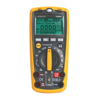
DVM601
22/08/2013 ©2008 Velleman
®
Components nv
8
• For continuity tests, connect the test leads to two points of the circuit to
be tested. If continuity exists (resistance < 50Ω), the built-in buzzer will
sound. If the circuit is open, “OL” will be indicated.
Non-contact AC voltage test
• Set the rotary switch [3] to any position (except OFF).
• The AC-sensor is located at the top of the meter, near the light sensor
[9]. Point the AC-sensor towards the suspected AC-source. When AC
voltage is present, the indicator [16] will light up. The stronger the AC-
source, the more the indicator [16] will be lit.
7. Battery
• When the low battery indication ( ) appears, replace the internal
batteries. Turn the rotary switch [3] to the OFF-position.
• Always disconnect test leads when replacing the battery. Do not us the
device without batteries installed.
• The battery cover is located on the back of the device and is closed with two
screws. Remove the screws and open the battery compartment.
• Remove the battery and insert a new 9V (E-block) battery following the
polarity as indicated in the battery holder.
• Reinstall the cover and secure it with the two screws.
•
Remove the battery when the device is not in use for a longer period of time to
avoid leakage.
• Do not attempt to recharge non-rechargeable batteries, do not puncture and do
not throw in fire as they may explode.
WARNING: handle batteries with care, observe warnings on
battery casing. Dispose of batteries in accordance with local
regulations.
Keep batteries away from children.
8. Fuses
• To replace an internal fuse, turn the rotary switch [3] to the OFF-position.
• Always disconnect test leads when replacing fuses. Do not use the device
without the proper fuses installed.
• The access the fuses, the whole back cover must be removed. Loosen the 6
outer screws (2 are located under the foldable stand). Do not remove the
battery cover screws (see §7). Lift the whole back cover. Do not touch the
electronic circuitry inside.
• Replace fuses only by new ones with following specifications:
• Fuse 1 (large): F 10A/600V fast blow
• Fuse 2 (small): F 500mA/660V fast blow
Using wrong fuses or short-circuiting fuse holders can lead to
potentially life-threatening situations.
• Close the back cover and secure the 6 screws.