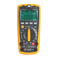
DVM601
22/08/2013 ©2008 Velleman
®
Components nv
7
the red lead connection.
• Press the Hz/% button to switch to frequency; press again to see the
duty cycle (%).
*: no auto-ranging for AC
AC/DC current measurement
• Connect the red test lead to the µA/mA [6] input jack (max. 400mA) or
10A [7] input jack and the black test lead to the COM jack [5].
• Set the rotary switch [3] in the desired current range (<4mA: µA ,
<400mA: mA , <10A: 10A ) and use the mode button [3] to
choose between AC and DC current.
• Open the circuit in which the current is to be measured and connect the
test leads to the circuit IN SERIES.
• Read the current value and the polarity of the red lead connection on the
LCD display.
Resistance, diode test and audible continuity test
• Connect the red test lead to the Ω-jack [4] and the black test lead to the
COM jack [5] (the red lead has a positive polarity "+").
• Set the rotary switch [3] in the Ω range position. Do not apply input
voltage at this setting!
• Use the mode button [13] to choose between Ω, diode or continuity test.
• If the resistance being measured is connected to a circuit, turn off the
power and discharge all capacitors before applying the test probes.
• Connect the test leads to the resistor to be measured and read the LCD
display.
Note: wait a few seconds for a stable reading when measuring resistors >
1MΩ.
400.0Ω 0.1Ω 40.00KΩ 10Ω 4.000MΩ 10kΩ
• For diode tests, connect the red test lead to the anode of the diode to be
tested and the black test lead to the cathode of the diode. The approx.
forward voltage drop of the diode will be displayed (typically 0.400 –
0.700V). If the connection is reversed, the display will show “OL”.

 Loading...