EasyManua.ls Logo

Velleman K2579 User Manual

Velleman K2579
12 pages
To Next Page IconTo Next Page
Page #1 background imageLoading...
Page #1 background image
K2579
ILLUSTRATED ASSEMBLY MANUAL H2579IP-1
Total solder points: 49
Difficulty level: beginner 1 2 3 4 5 advanced
S
m
al
l
s
i
z
e
t
i
m
er
pr
ov
i
de
s
up
t
o
60
m
i
nut
e
s
d
el
ay
.
UNIVERSAL START/STOP TIMER
Specifications
Relay output with switchover contact.
Power supply : 12VDC regulated.
Typical active current : 55mA.
Relay output : 2A/240V max.
 Dimensions : 38x69mm / 1.5”x2.7”.
Question and Answer IconNeed help?

Do you have a question about the Velleman K2579 and is the answer not in the manual?

Velleman K2579 Specifications

General IconGeneral
WaterproofNo
Product colorMulticolor
Battery type-
Display size (HxV) (imperial)0 \
Weight and Dimensions IconWeight and Dimensions
Dimensions (WxDxH)38 x 69 x 25 mm

Summary

Features & Specifications

Product Features Overview

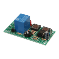
Details the main features of the K2579 universal start/stop timer.

Technical Specifications

Lists the electrical and physical specifications of the timer module.

Assembly Guidance

Tools and Preparation

Provides a guide to the necessary tools and preparation steps for successful assembly.

Assembly Procedures

Guides the assembly process, including reading instructions and checking progress.

Soldering Techniques

Details proper soldering methods for component leads, ensuring quality joints.

Component Installation Steps

Diode and Resistor Installation

Instructions for installing diodes and resistors, noting polarity and values.

Capacitor and Transistor Installation

Guidance on installing capacitors, transistors, and potentiometers, with polarity notes.

LED and IC Socket Installation

Steps for installing the LED, IC socket, and the IC itself.

Push Buttons and Relay Installation

Push Button Installation

Instructions for mounting the start and stop push buttons.

Relay Installation

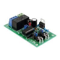
Guidance on installing the relay module.

Connection Example

Hook-up and Use

PCB Layout

Circuit Diagram

Related product manuals