Do you have a question about the Velleman K8055 and is the answer not in the manual?
Details on 5 digital inputs and on-board test buttons.
Details on 2 analog inputs with attenuation/amplification.
Details on 8 digital open collector output switches with LED indication.
Details on 2 analog outputs with PWM capability and LED indication.
CPU, connection, OS, and CD ROM requirements.
Instructions on mounting components and soldering leads properly.
Guidance on achieving cone-shaped, shiny solder joints.
Explanation and formula for calculating gain factors A1 and A2.
Guide to installing the K8055 demo software from CD or website.
Instructions for initial setup before testing, including address selection.
Steps to connect the USB cable and verify power/operation.
Detailed electrical schematic of the K8055 board.
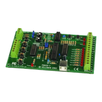
Visual guide showing component placement on the PCB.
| Brand | Velleman |
|---|---|
| Model | K8055 |
| Category | Recording Equipment |
| Language | English |