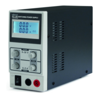
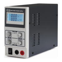
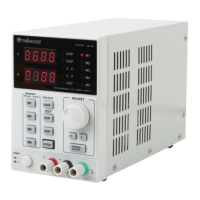
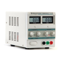
LABPS3005N
V. 05 – 18/05/2022 5 ©Velleman Group nv
Using the Current-Limiting Adjustment in C.V. Mode
2. Turn both the current adjustment knobs fully anticlockwise to the minimum, and
the voltage adjustment knobs fully clockwise to the maximum.
3. Short-circuit the output terminals by interconnecting them with the appropriate
cable (60 V/16 A DC cable).
4. Turn the current adjustment knob to the required current-limiting value. Use the
fine-tune knob if desired (where applicable). The C.C. indicator lights on the
display.
5. Remove the short-circuit cable from both output terminals.
6. Turn the voltage adjustment knob to the required value. Use the fine-tune knob if
desired (where applicable). The C.V. indicator lights up on the display.
7. Connect the load to the output terminals. If the current exceeds the current-
limiting point, the C.C. indicator lights up on the display.
• You can read the output current and the output voltage from the display as soon as
the device has been switched on.
• The C.V. indicator is lit if the device is in the C.V.-mode.
• The C.V. LED is off and the C.C. LED will light if the Amp display indicates a value
that exceeds the installed value. When this happens, the device will automatically
go into current-limiting mode. Install a load that will allow the device to function
normally.
6. Cleaning and Maintenance
• Disconnect the device from the mains prior to maintenance activities.
• The power supply cables must not show any damage. Have a qualified technician
maintain the device.
• Wipe the device regularly with a moist, lint-free cloth. Do not use alcohol or
solvents.
• There are no user-serviceable parts, apart from the fuse. Contact your dealer for
spare parts if necessary.
• Store the device in a dry, well-ventilated, dust-free room.
7. Technical Specifications
input voltage .......................................................... 220-240 V~ (± 10 %), 50/60 Hz
voltage .............................................................................................0-30 VDC
current ................................................................................................... 0.5 A
power ........................................................................................... 150 W max.
cos Phi ..................................................................................................... 0.82
fuse .................................................................................................. 3.15 A, 250 V
ripple voltage .................................................................................. ≤ 1.0 mV (rms)
ripple current ........................................................................................ 3 mA (rms)
operating temperature ................................. 0 °C to +40 °C, < 90 % relative humidity
 Loading...
