PCS500 / PCS100 / K8031
12
SOFTWARE CONTROLS
Remarks:
• Due to software upgrades, the actual menus can differ from the ones
described in this manual, please also refer to the Help file (English only)
• PCS100 / K8031 has only one channel and no external trigger input
All modules:
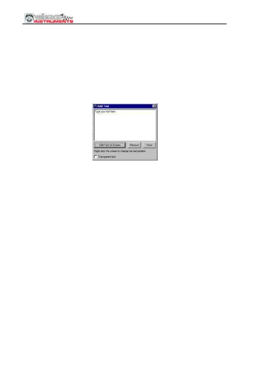
How to add a comment in the signal screen:
Right mouse Click into the screen
Text box will open, to write your comment:
Click “Add text on the screen” or “Remove” to remove previously inserted text.
Right click on the screen to position your text.
Click “Close”
To make the text transparent with the background, check “Transparent text”
The text will have the same color as the vertical time/frequency markers.
Oscilloscope mode (DSO)
VOLTS/DIV
Selected value indicates the peak-to-peak voltage required to produce a
peak-to-peak deflection of one major division on the screen.
The vertical position sliders move the trace in Y position.
CH1, CH2
Buttons turn the display of the trace ON or OFF. To get the cursor
measurements of CH2 voltage values switch CH1 off.
COUPLING
AC: the input signal is capacitive coupled to the input amplifier/attenuator. Only
the AC components are measured.
GND: (not for K8031) the input signal is broken and the input
amplifier/attenuator is connected to earth. Use this position for selecting a
reference point on the display.
DC: the input signal is directly connected to the input amplifier/attenuator. Both
AC and DC voltage are measured.
 Loading...