Do you have a question about the Velleman EDU06 and is the answer not in the manual?
Introduces different types of signal waveforms displayed on oscilloscopes.
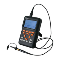
Details the oscilloscope probe, its parts, and functions.
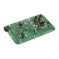
Instructions on powering the oscilloscope tutor board and initial checks.
States the learning objective for measuring AC voltage.
Step-by-step instructions for conducting the AC voltage measurement.
Describes the expected waveform and readings on the oscilloscope.
States the learning objective for measuring adjustable AC voltage.
Guides on adjusting AC voltage using the trimmer and observing the scope.
States the objective of measuring frequency and period using markers.
Details using oscilloscope markers to measure signal frequency and period.
Demonstrates the appearance of single-phase rectified AC on an oscilloscope.
Explains how a single diode affects AC voltage to produce rectified DC.
Shows dual-phase rectified AC and its difference from single-phase.
Explains the use of a diode bridge for dual-phase rectification.
Practice measuring period and frequency of rectified signals.
Shows smoothed/unsmoothed DC and how to assess DC supply quality.
Explains the role of capacitors in smoothing DC voltage and the concept of ripple.
Demonstrates measuring the amount of ripple voltage on a DC signal.
Explains how dual-phase rectification reduces ripple.
Shows that oscilloscopes are suitable for measuring DC voltages.
Explains the importance of setting DC input coupling for DC measurements.
Guides on setting the DC reference for accurate voltage readings.
Demonstrates measuring voltage at different points in a divider circuit.
Illustrates the effect of swapping probe and ground on readings.
Demonstrates the use of the oscilloscope's trigger function.
Explains the function of the trigger circuit and slope symbol.
Practice adjusting trigger level for stable waveforms.
Explains how the slope symbol affects waveform triggering.
| Category | Test Equipment |
|---|---|
| Model | EDU06 |
| Display | LCD |
| Output Waveforms | Sine, Square, Triangle |
| Educational Purpose | Yes |
| Manual Included | Yes |
| Measurement Functions | Voltage, Current, Resistance |
| Battery | 9 V |
| Frequency Range | 1 Hz to 1 MHz |
| Output Impedance | 600 Ohm |
| Power Supply | AC adapter or battery |
| Components | Probes |