7
Experiment 2: Adjustable AC voltage
(advantages of the auto-setup function)
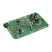
Connection layout:
Connection summary:
GND clip : 2
Probe tip : 3
Purpose:
The purpose of this experiment is to show the advantages of the auto-setup function to measure AC
voltage.
How?:
Turn on the HPS140 Handheld Pocket Scope 1. (see HPS140 manual for How-To instructions).
Place the probe switch “x1/x10” to ‘x1’.2.
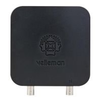
Trimmer RV1 allows us to adjust the output voltage on test
point 3 between 0V and the full input voltage. Turn RV1 fully
anti-clockwise (0V output). The trace on our oscilloscope
screen remains a fl at line, as there is no input voltage.
Next, set V/div to 50mV/div
(see HPS140 manual for How-To instructions).
Slightly turn RV1 clockwise until a sine wave is displayed on
the screen. You only need to turn it slightly before the signal
appears. If the signal goes ‘off-screen’, turn RV1 anti-clock-
wise until the signal is correctly displayed. In the lower right
hand corner, you can read the current RMS value of the AC
voltage measured, e.g. 100mV (0.1V)
Exp.2: Adjustable AC voltage (advantages of the auto-setup function)
NOTES: