Do you have a question about the Velleman PCS500 and is the answer not in the manual?
Key specifications for the PCS500 oscilloscope model.
Key specifications for the PCS100 / K8031 oscilloscope models.
PC hardware and software prerequisites for operation.
Detailed technical parameters for PCS500 and PCS100/K8031.
Description of the transient recorder function and its parameters.
Description of the spectrum analyzer function and its parameters.
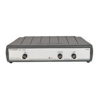
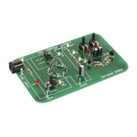
Overview of BNC inputs, trigger, power, parallel port, and test signal.
Details connecting the unit to PC port and power adapter.
Advice on using X10 probes for high voltage/impedance measurements.
Explains DSO function and how it digitizes signals for analysis.
Explains FFT for frequency spectrum analysis and harmonics.
Covers adding comments, VOLTS/DIV, CH1/CH2, and coupling settings.
Details TIME/DIV, trigger source, level, edge, and run/single modes.
Explains X-POSITION scrollbar and S/L interpolation for display.
Describes the RIS/ETS sampling mode for repetitive signals.
Covers math operations (Ch1+Ch2, Ch1-Ch2, XY Plot) and auto setup.
Sets frequency range, scale (LOG/LIN), and zoom for FFT analysis.
Covers saving images/data and printing options.
Details calibration procedure and program termination.
Covers copy/paste, FFT windows, and display averaging.
Guides on selecting the LPT port address for hardware communication.
Customizes display colors and selects RMS or dBm value display.
Utilizes markers for voltage, time, and frequency measurements.
Details mathematical operations and accessing the help file.
Explains recording short-term signals with a slow time base for analysis.
Details controls for voltage, channels, and coupling in REC mode.
Details timebase, run modes, and horizontal positioning for REC.
Covers saving data, auto-save, and printing setup.
Details clipboard operations for copying and pasting data.
Configures markers for measurements and adjusts grid brightness.
Accesses help file and displays program version.
Addresses issues like no signal, communication errors, and BIOS settings.
Covers voltage readout discrepancies and recorder time scale errors.
| Timebase | 5 ns/div to 10 s/div |
|---|---|
| Input Coupling | DC, AC and GND |
| Resolution | 8-bit |
| Trigger Modes | Auto, Normal and Single |
| Input Impedance | 1 Mohm // 30 pF |