PCS500 / PCS100 / K8031
8
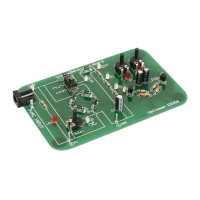
CONNECTIONS
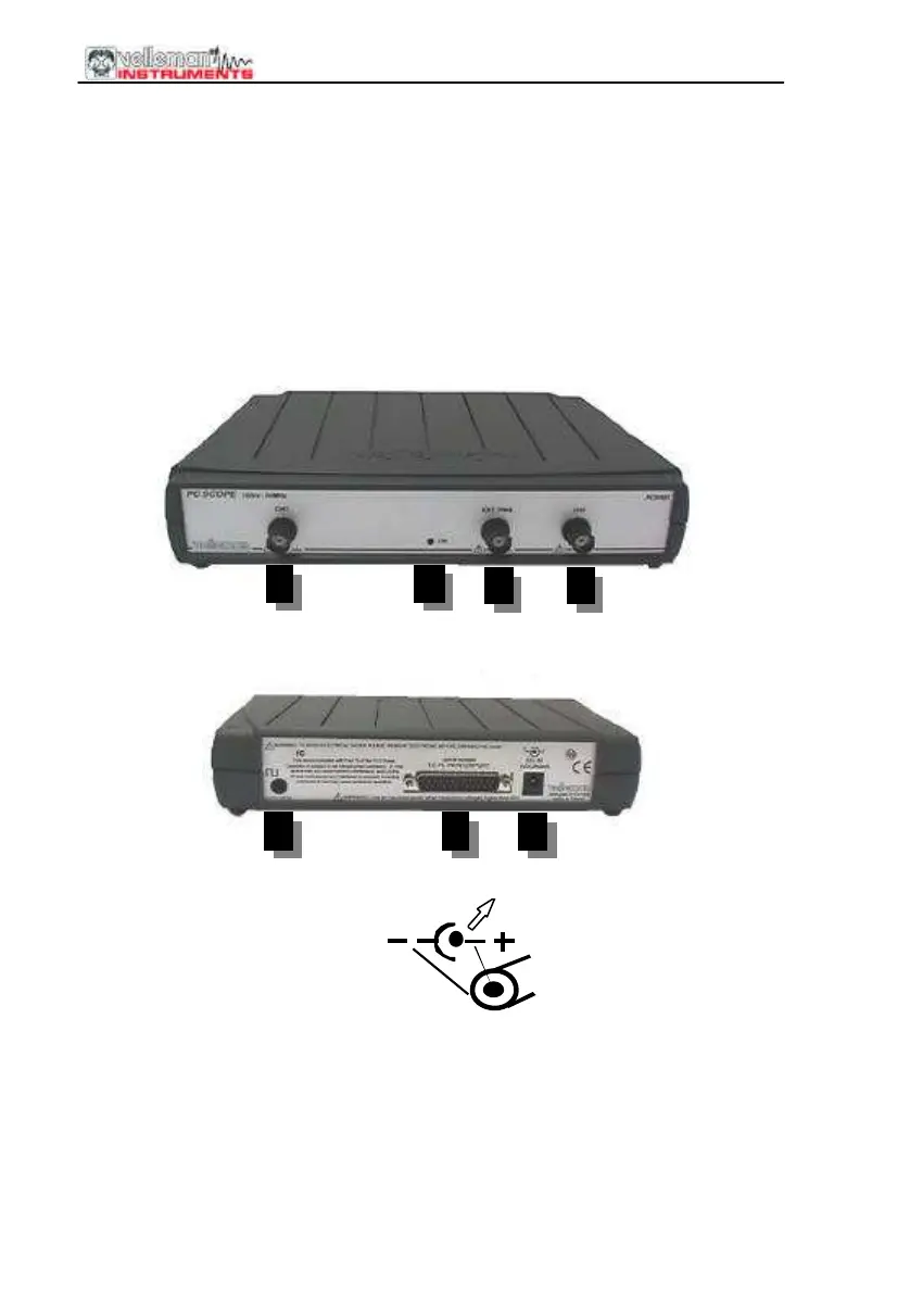
Survey of the connections and controls
1.BNC input connectors (1CH for PCS100 / K8031)
2.BNC external trigger input (max. input 100Vp AC+DC) only PCS500
3.Power indication LED (software driven)
4.Adapter connection (observe the polarity!)
5.Parallel port connector
6.X10 probe testing signal (at front panel for PCS100 / K8031)
PCS500 PICTURES
1 2
3
1
4 6 5
The unit is connected to the printer port LPT of the computer, using a parallel
cable.