PEM10D2 Rev.01
06.12.2010 6 ©Velleman nv
whenmountingthesystemtoolow,analarmmightaccidentallybe
triggeredbysmallanimalse.g.pets.
• Removethemountingbracket[B]fromthehousingbyreleasingthe
twomountingbolts[J].
• Usethemountingbracket[B]asatemplatetodeterminethe
positionofthemountingholesandmountthebracketwith2screws.
• Whenthecableneedstogothroughawallcutawaythewallcable
hole[K];hangthehousingoverthemountingbracketandmarkthe
locationofthecablehole.Removethehousinganddrilltheholeand
providethenecessarycabling.Mounttheincludedrubbersealinthe
wallcablehole.
• Whenthecablerunsontopofthewallcutawaytheholeatthe
bottomofthehousingandmountthecablegland[I]intheopening
(donottightenthenutthatcoverstheconicalpart).Providethe
necessarycabling.
• Guidethecontrolcablesthroughthebackorcableglandofthe
housing.Tightenthecablegland.
• Maketheproperconnectionstotheterminals(see§5).
Note:tofacilitatetheconnectionsofthewiring,liftthesensor
assemblyfromthehousing.Todothis,releasethe4screws[L](2
largeonesontop,2smallonesnearthebottom).Aftermakingall
connectionsgentlyreseatthesensorassemblyandputthe4
screwsback.
• Attachthehousingtothemountingbracketandsecureitwiththe
twomountingbolts[J].
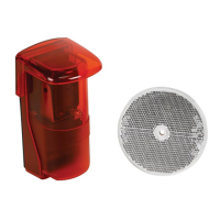
• Applypowertothesystem.ThealignmentLED[D]willturnredsince
noreflectorisdetected.
• Placethereflectorinlinewiththetransmitter/receiverlens[C]until
thealignmentLED[D]turnsgreen.Markthepositionofthereflector
andmountitinthatlocation.
Note:thelenscanbealignedhorizontally(±25°)byrotatingthe
entirelenshead(donotforce)orverticallyusingthevertical
alignmentbolt[F].
• Closethecover[H]withthe4screwsandslidethehood[A]inplace.
Note:byclosingthecover,thetamperswitch[E]ispressedandthe
tampercontact[6]/[7]isclosed.
7. Operation
• Whenthebeambetweentransmitterandreceiverisbroken,the
alignmentLED[D]turnsredandanalarmistriggeredontheoutput
contactsuntilthebeamisrestored:
[3]‐[5]:opencontact
[4]‐[5]:closedcontact