PEM10D2 Rev.01
06.12.2010 5 ©Velleman nv
• Onlyusethedeviceforitsintendedpurpose.Usingthedeviceinan
unauthorisedwaywillvoidthewarranty.
• Damagecausedbydisregardofcertainguidelinesinthismanualis
notcoveredbythewarrantyandthedealerwillnotaccept
responsibilityforanyensuingdefectsorproblems.
• Theuserisresponsiblefortheproperconnectionandfunctioningof
thedeviceandthefollowupofpossiblealarmoutputs.Vellemannv
cannotbeheldresponsibleforanylossofgoodsorotherdamage
causedbyneglectingalarmconditionsorduetomisuseor
malfunctioningofthedevice.
• Keepthismanualforfuturereference.
4. Features
• Waterproof
• ledindicatorforbeamalignment
• tamperswitch
• anti‐fog/dew/raincover
• comeswithmountingaccessories
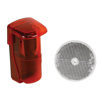
5. Overview
Refertotheillustrationsonpage2and3ofthismanual.
A hood G terminals
B mountingbracket H cover
C transmitter/receiver lens I gland
D alignmentLED J mountingbolt
E tamperswitch K wallcablehole
F verticalalignment bolt L screw(4x)
Terminals
1 inputvoltage inputvoltage12~250V ACorDC(nopolarity)
2 inputvoltage
3 NC outputcontacts
normallyclosedbetween3and5
Normallyopenbetween4and5
4 NO
5 COM
6 TP1 tampercontact:openwhentamperswitchis
pressed(coverisclosed)
7 TP2
6. Installation
• Determinealocationforthesystem.Avoiddirectsunlightonthe
transmitter/receiverlens[C]andnotethatthemaximumdistanceto
thereflectoris10m.Makesuretopointtowardsaflatsurfaceto
whichthereflectorcaneasilybemounted.Alsokeepinmindthat