Do you have a question about the Velleman VMA409 and is the answer not in the manual?
Information on proper disposal of the device and batteries to protect the environment.
Covers child usage, supervision, indoor-only operation, and protection from liquids.
Covers warranty, responsible usage, product appearance, temperature acclimatization, and manual retention.
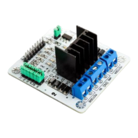
This module provides full control for two DC motors or one stepper motor.
Key technical details including power, current, temperature, and dimensions.
Example Arduino code and connection for controlling a 2-channel DC motor.
Wiring connections for the L298N module to Arduino pins for DC motor control.
Example Arduino code and connection for controlling a 2-phase stepper motor.
Wiring connections for the L298N module to Arduino pins for stepper motor control.
Explains the 24-month warranty for consumer products and conditions not covered.
Details on how to submit articles for repair and tips for cost savings.
The VMA409 is a versatile L298N Dual Bridge DC Stepper Controller Board designed for controlling two DC motors or one stepper motor, making it a valuable component for various prototyping and automation projects. This module integrates seamlessly with Arduino® platforms, an open-source prototyping environment known for its ease of use in hardware and software development. Arduino® boards are capable of reading inputs from sensors or buttons and translating them into outputs, such as activating motors or turning on LEDs. The VMA409 leverages this capability, allowing users to implement complex motor control through simple programming instructions written in the Arduino programming language.
At its core, the VMA409 serves as an interface between a microcontroller, like an Arduino board, and motors. It utilizes the L298N driver, a robust integrated circuit capable of driving inductive loads such as relays, solenoids, DC, and stepper motors. The "dual bridge" aspect refers to its ability to control two separate DC motors independently or to manage the two phases of a single stepper motor. This flexibility makes it suitable for a wide range of applications, from robotics and automation to educational projects.
For DC motors, the VMA409 allows for control over both direction and speed. By manipulating the input pins (IN1, IN2 for motor 1; IN3, IN4 for motor 2) and the enable pins (ENA for motor 1; ENB for motor 2), users can dictate whether a motor spins clockwise or counter-clockwise, and at what velocity. Speed control is typically achieved through Pulse Width Modulation (PWM) signals applied to the enable pins, allowing for fine-grained adjustments to motor output. This precise control is crucial for applications requiring variable speed, such as conveyor belts or robotic arms.
When configured for a stepper motor, the VMA409 facilitates precise positional control. Stepper motors move in discrete steps, making them ideal for applications where exact positioning is required, such as 3D printers, CNC machines, or camera pan/tilt systems. The board's dual-bridge design allows it to energize the different coils of a stepper motor in a specific sequence, causing the motor to rotate by a precise angle. The control pins (IN1-IN4) are used to define the stepping sequence, while the enable pins can still be used for overall motor activation.
The VMA409 also includes provisions for power management. It requires a power input for the motors (VMS) and a separate power input for its internal logic circuit (5V). This separation ensures that the potentially noisy motor power supply does not interfere with the sensitive logic operations, contributing to stable and reliable performance. The board also offers a 5V output, which can be used to power other low-power components in the system, simplifying wiring and power distribution.
Current testing pins (CSA and CSB) are integrated into the design, offering a valuable feature for monitoring motor current. These pins can be wired to a resistor for current measurement, allowing users to detect overcurrent conditions or to implement current-limiting strategies. Alternatively, they can be tied to a jumper to disable this feature if not needed. This capability is particularly useful for protecting motors and the driver board from damage due to excessive current draw, which can occur under heavy loads or during motor stalls.
The inclusion of pull-up resistors (UR1-UR4) on the board is another thoughtful design choice. Pull-up resistors ensure that input pins have a defined state when no external signal is applied, preventing floating inputs that can lead to unpredictable behavior. This enhances the reliability and robustness of the control system, especially in environments where electrical noise might be present.
A 5V source jumper (5V_EN) provides flexibility in how the logic circuit is powered. When enabled, this jumper allows the logic circuit to draw power from the VMS port, simplifying the power setup by using a single supply for both motors and logic, provided the VMS voltage is within an acceptable range for the logic. When disabled, the logic circuit is powered by the dedicated 5V port, offering greater isolation and potentially more stable operation for the logic.
The VMA409 is designed with user-friendliness in mind, particularly for those familiar with the Arduino ecosystem. Its straightforward pin layout and clear labeling make it relatively easy to connect to an Arduino board and motors. The module's compact dimensions allow for integration into various projects without requiring excessive space.
For controlling DC motors, users can implement simple code to set motor direction and speed. By sending HIGH or LOW signals to the IN pins, the direction of rotation can be toggled. Speed control is achieved by applying PWM signals to the ENA and ENB pins, allowing for smooth acceleration and deceleration. This makes it suitable for applications requiring variable speed, such as small robots, fan controllers, or automated blinds. The ability to control two DC motors independently means that differential drive systems, common in mobile robotics, can be easily implemented.
When using a stepper motor, the VMA409 enables precise control over angular position. Users can define the number of steps per revolution and then command the motor to move a specific number of steps in either direction. This is invaluable for applications like 3D printers, where precise movement of print heads is critical, or in camera gimbals for accurate panning and tilting. The Arduino Stepper library simplifies the programming process, abstracting away the complexities of generating the correct stepping sequences.
The board's compatibility with a wide range of input voltages for the motor power supply (VMS) makes it adaptable to different motor types and power sources. This flexibility means users are not restricted to a single voltage level, allowing them to choose motors that best fit their project requirements.
The current test pins (CSA, CSB) are a practical usage feature for advanced users or those developing robust systems. By monitoring motor current, users can implement software-based overcurrent protection, detect motor stalls, or optimize power consumption. This adds a layer of intelligence and safety to motor control applications.
The inclusion of pull-up resistors simplifies circuit design by eliminating the need for external components to ensure stable input states. This reduces component count and wiring complexity, making the setup cleaner and less prone to errors.
The 5V source jumper (5V_EN) offers a convenient way to manage power for the logic circuit. For simpler setups, powering the logic from the VMS port can reduce the number of power supplies required. For more critical applications, using a separate 5V supply for the logic ensures maximum stability and isolation, which can be crucial in noisy electrical environments.
While the VMA409 is a robust and generally low-maintenance device, adherence to certain guidelines can ensure its longevity and reliable operation. The manual emphasizes the importance of proper environmental conditions, recommending indoor use only and protection from rain, moisture, splashing, and dripping liquids. This prevents corrosion and short circuits, which can severely damage the electronic components.
Regular visual inspection of the board for any signs of physical damage, such as bent pins, cracked solder joints, or burnt components, is a good practice. Although the device is designed to be durable, mishandling or accidental impacts can cause damage. If any damage is observed, it is recommended not to use the device and to contact the dealer for assistance.
The integrated heat sink on the L298N driver chip is a key maintenance feature, as it helps dissipate heat generated during operation. Driving motors, especially under heavy loads, can cause the driver chip to heat up significantly. The heat sink ensures that the chip operates within its safe temperature limits, preventing thermal damage and extending its lifespan. Users should ensure that the heat sink is not obstructed and has adequate airflow, especially in enclosed spaces.
The current test pins (CSA, CSB) can also be considered a maintenance feature, as they allow for diagnostic checks. By monitoring motor current, users can identify potential issues such as motor binding, excessive load, or short circuits in the motor windings before they lead to catastrophic failure. This proactive monitoring can help in troubleshooting and preventing damage to both the motors and the driver board.
The general guidelines provided in the manual highlight several important aspects of device maintenance and care. These include using the device only for its intended purpose, avoiding unauthorized modifications, and familiarizing oneself with its functions before use. Unauthorized modifications can compromise safety and void the warranty.
Proper handling during installation and removal is also crucial. Ensuring that connections are made correctly and securely prevents intermittent operation or damage due to loose contacts. When storing the device, it should be kept in a dry, cool environment, away from extreme temperatures and humidity, to prevent degradation of components.
In case of temperature changes, such as moving the device from a cold to a warm environment, it is advised not to switch it on immediately. Allowing the device to reach room temperature prevents condensation from forming inside, which could lead to short circuits and damage. This simple precaution can significantly contribute to the device's reliability.
Finally, keeping the user manual for future reference is a maintenance practice in itself. The manual contains valuable information regarding pin layouts, example code, and troubleshooting tips, which can be indispensable for resolving issues or understanding the device's capabilities over time. Adhering to these maintenance practices ensures the VMA409 remains a reliable and effective component in any motor control project.
| Type | LED Matrix Controller |
|---|---|
| Output Voltage | 5V |
| Output Channels | 16 |
| Control Method | I2C |
| LED Driver | HT16K33 |
| Matrix size | 8x8 |
| Interface | I2C |
| Input Voltage | 5V |
| I2C address | 0x70 (default) |