EasyManua.ls Logo

Vemer HT NTC-2P3D User Manual

Vemer HT NTC-2P3D
32 pages
To Next Page IconTo Next Page
Page #1 background imageLoading...
Page #1 background image
 



Question and Answer IconNeed help?

Do you have a question about the Vemer HT NTC-2P3D and is the answer not in the manual?

Vemer HT NTC-2P3D Specifications

General IconGeneral
Protection DegreeIP20
StandardsEN 60730-1, EN 60730-2-9
Power supply230V AC
Output Voltage230V AC
Operating Temperature0°C to 40°C
Relative HumidityMax 90% non-condensing

Summary

Safety Warnings

Installation and Operation Safety

Provides essential safety instructions for installation and operation of the instrument.

Technical Specifications

Key Features and Specifications

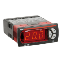
Outlines the key features, display capabilities, and performance specifications of the regulators.

Parameter Settings and Operating Modes

Covers configurable parameters and various regulation/operation modes available for the instruments.

Electrical Connections

Wiring and Connection Guidelines

Emphasizes adherence to safety warnings and connection diagrams for proper wiring.

Operation and Parameter Configuration

Normal Operation and Simplified Setup

Describes normal functioning and the process of simplified parameter programming.

Advanced Configuration and Menu Structure

Details accessing advanced settings and outlines the structure of eight parameter menus.

Parameter Menu Overview

Parameter Descriptions - Regulation & Output

[REG] Regulation Menu Parameters

Details parameters like set-point, differential, and neutral zone for regulation.

[OUT] Output Menu Parameters

Lists parameters for handling time, minimum ON/OFF times, and PWM cycle.

Parameter Descriptions - Input

[ING] Outside Input Menu Parameters

Explains digital input functions, delay, and output status settings.

Parameter Descriptions - Alarm & Display

Parameter Descriptions - Sensor & System

Parameter Descriptions - Special

Parameter Dependencies and Error Messages

Message Types and Output Status

Lists messages for sensor errors, minimum/maximum alarms, and outside input alarms.

33x75 mm Rear Panel Connection Diagrams

72x72 mm Rear Panel Connection Diagrams

4 DIN Modular Connection Diagrams

Related product manuals