Do you have a question about the Vemer HT NiPt Series and is the answer not in the manual?
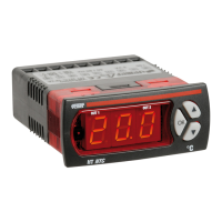
Details the 3-digit LED display and its range capabilities.
Explains the LED indicators for relay status (ON/OFF/timing).
Describes the function of the three parameter setting keys.
The target value for maintaining a required measurement level.
Maximum permitted variation from set point before appliance intervention.
Regulator increases cooling as temperature rises; decreases heating as temp falls.
Regulator increases heating as temperature falls; decreases cooling as temp rises.
Range around set point where no output is activated.
Relays activated periodically in impulse mode, modulating power based on measurement position.
All outputs operate in direct mode with set point 1 and differential 1.
All outputs operate in reverse mode with set point 1 and differential 1.
Output 1 in reverse, output 2 in direct, within a neutral zone.
PWM regulation with neutral zone, relays activated impulsively.
Outputs switch between direct and reverse based on digital input status.
Outputs switch between set points/differentials based on digital input status.
Outputs operate in reverse, switching set points/differentials via digital input.
Channel 1 in reverse, Channel 2 in direct, using different set points/differentials.
Output 1 for reverse operation, Output 2 dedicated to alarm.
Appliance operates with set parameters, displaying measured temp and output status.
Method to modify regulation menu parameters by pressing the OK key.
Method to access and modify parameters via eight organized menus.
Details parameters for set-point, differential, and neutral zone settings.
Details parameters for relay timing, start-ups, and PWM cycle time.
Details parameters for digital input function, delay, and output status.
Details parameters for probe alarm, min/max shifts, delay, and buzzer.
Details parameters for set point limits, offset, resolution, and measurement unit.
Details parameters for sensor type, cold joint correction, and display.
Details parameters for password, modification enable, and operating mode.
Details parameters for special operating modes, output dependence, and logic.
Wiring diagram for the HT NiPt-1P3D model.
Wiring diagram for the HT NiPt-1P3A model.
Wiring diagram for the HT NiPt-2P3D model.
Wiring diagram for the HT NTC-1P3D model.
Wiring diagram for the HT NTC-1P3A model.
Wiring diagram for the HT NTC-2P3D model.
Wiring diagram for the HT JK-1P3A model.
Wiring diagram for the HT JK-1P3D model.
Wiring diagram for the HT JK-2P3D model.
Wiring diagram for the HT NiPt-1P7A model.
Wiring diagram for the HT NiPt-2P7A model.
Wiring diagram for the HT NTC-1P7A model.
Wiring diagram for the HT NTC-2P7A model.
Wiring diagram for the HT JK-1P7A model.
Wiring diagram for the HT JK-2P7A model.
Wiring diagram for the HT NiPt-1DA modular model.
Wiring diagram for the HT NiPt-2DA modular model.
Wiring diagram for the HT NTC-1DA modular model.
Wiring diagram for the HT NTC-2DA modular model.
Wiring diagram for the HT JK-1DA modular model.
Wiring diagram for the HT JK-2DA modular model.
| Brand | Vemer |
|---|---|
| Model | HT NiPt Series |
| Category | Controller |
| Language | English |