- 38 -
User Manual Digital Heat Regulators
English
Reverse operating mode with set point and differential switching
from digital input. [PRO=8]
• In this mode, both outputs operate in reverse, with set point 1/differential 1 or set
point 2/differential 2, depending on the status of the digital input.
More precisely, with set point 1/differential 1 if the digital input is open and set
point 2/differential 2 if closed. The operating modes are the same as mode 1.
It is necessary to set both values of the set points [ST1] and [ST2] and
differentials [DF1] and [DF2].
Operating mode with channels 1 and 2 in reverse with set point 1
and differential. 1 and direct with set point 2 and differential 2
[PRO=9] respectively.
• In this mode, output 1 operates in reverse and output 2 in direct. It is necessary
to set the values of set point 1 [ST1] and differential 1 [DF1] for output 1,
and set point 2 [ST2] and differential 2 [DF2] for output 2.
The operating modes are the same as modes 0 and 1.
If there is a single output, this will operate in reverse.
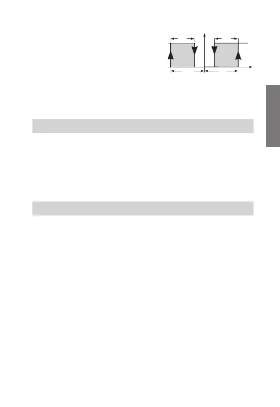
Alarm operating mode [PRO=10]
• In this mode, output 1 operates in reverse (with neutral zone), and output 2 is
dedicated to the alarm. It is necessary to set the values of set point 1 [ST1],
- 39 -
User Manual Digital Heat Regulators
English
differential 1 [DF1] and the neutral
zone [DB1] for output 1 and all the
alarm menu parameters for output 2.
The maximum alarm will be
activated when the value
[ST1]+[HIA] is reached and will
be deactivated at value
[ST1]+[HIA]-[DFA]. The minimum
alarm will be activated when the
value [ST1]-[LOA] is reached and will be deactivated at value [ST1]-[LOA]+[DFA].
When there is a single output, this will be dedicated to the alarm in the same way.
Normal operation
The appliance operates in this way when no parameters are being programmed.
In this status, the instrument carries out the regulation on the basis of the tempera-
ture measured and the parameters set. The following information is displayed:
• The temperature measured by the sensor
• The status of outputs OUT1 and OUT2
There are two types of programming for the setting of the regulation parameters:
- Simplified programming
- Advanced programming
Note: to reset the default values set in the factory, switch on the
instrument while holding down the OK key.
Simplified programming
This is used to modify the regulation menu [REG] parameters only.
Access is gained to this type of programming by pressing the “OK” key.
Depending on the operating mode previously selected (see the system menu
[SYS]), the following parameters can be modified:
– set, differential (ON/OFF regulation)
– set, differential, neutral zone (ON/OFF regulation with neutral zone)
– set, differential, neutral zone (PWM regulation)
Use the “up” () key to scroll through the parameter labels in a
circular sequence.
Press the “down” () key at any time to leave the menu and return to normal
SETTING THE REGULATION PARAMETERS
OPERATION
 Loading...