- 42 -
User Manual Digital Heat Regulators
English
Description of parameters
• Inside the tables, the labels are presented in the same order as they appear in the
various menus of the instrument.
[REG] regulation menu
Notes:
(1) For values LO1/LO2 and HI1/HI2, see the display menu [DSP]
(2) Parameter active only if the operating mode permits
[OUT] output menu
Notes:
(3) This parameter enables the handling of the times defined by DON, TOF and TON for
each output channel, in the following ways:
0 timing not enabled for either relay output
1 timing enabled for relay 1 output only
2 timing enabled for relay 2 output only
3 timing enabled for relay 1 and 2 outputs
(4) this parameter limits the number of start-ups per hour for the driver connected to
the instrument (this parameter is frequently used for compressors, for example)
(5) the minimum time for which the output should remain ON
(6) timing enabled for relay 1 output only OFF
Labels of
parameters that
can be modified
Description
Parameter
values
default
notes
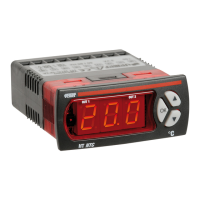
ST1 set-point 1 degrees LO1 HI1 20.0 (1)
DF1 Differential for set-point 1 degrees 0.1 100 2.0
ST2 set-point 2 degrees LO2 HI2 30.0 (2)
DF2 Differential for set-point 2 degrees 0.1 100 2.0 (2)
DBN Neutral zone (dead band) degrees 0 100 2.0 (2)
min max
unit
Labels of
parameters that
can be modified
Description
Parameter
values
default
notes
ETR Handling time on
relays enabled - 0 3 3 (3)
DON Minimum time between
2 start-ups of the same relay min 0 200 0 (4)
TOF Minimum relay ON time min 0 200 0 (5)
TON Minimum relay OFF time min 0 200 0 (6)
INI Initial delay from start-up
of instrument min 0 200 0 (7)
TCL PWM cycle time sec 1 200 200 (8)
min max
unit
- 43 -
User Manual Digital Heat Regulators
English
(7) the delay time for the driving of the outputs from the instant of instrument reset
(8) the period that can be set for PWM regulation. This item is displayed only if the
operating mode selected is PRO=5 (see system menu).
[ING] outside input menu
Notes:
(9) The values that can be set are:
0 Not active
1 Outside alarm (with contact open) with delay time “DID” and automatic
reset at the end of the alarm. The output status becomes “SUI”
2 Outside alarm (with contact open) with manual reset
3 The input operates as a switch: instrument on with contact closed and off
with contact open
4 The input operates as a switch for the display of the two probes S0 and S1
(contact open-probe S0, contact closed-probe S1)
The digital input function is excluded when one of the following
operating modes is selected inside the system menu [SYS]:
mode=6, mode=7 and mode=8
(10) This is the delay after which the instrument responds to a signal from the digital
input
(11) When the digital input is active and a time period “DID” has lapsed,
the outputs take on the following states:
0 Both relays OFF
1 Relay 1 ON and relay 2 OFF
2 Relay 1 OFF and relay 2 ON
3 Both relays ON
(12) This is the variation of the “Set” in degrees when the instrument switches
to night operation
Labels of
parameters that
can be modified
Description
Parameter
values
default
notes
TID Digital input function - 0 4 0 (9)
DID Digital input delay min 0 200 0 (10)
SUI Output status with digital
input active (open) - 0 3 0 (11)
DEL
Variation in night-time
temperature degrees -50.0 +50.0 5.0 (12)
min max
unit
 Loading...