2013.07 3 / 3
2. CONNECTIONS
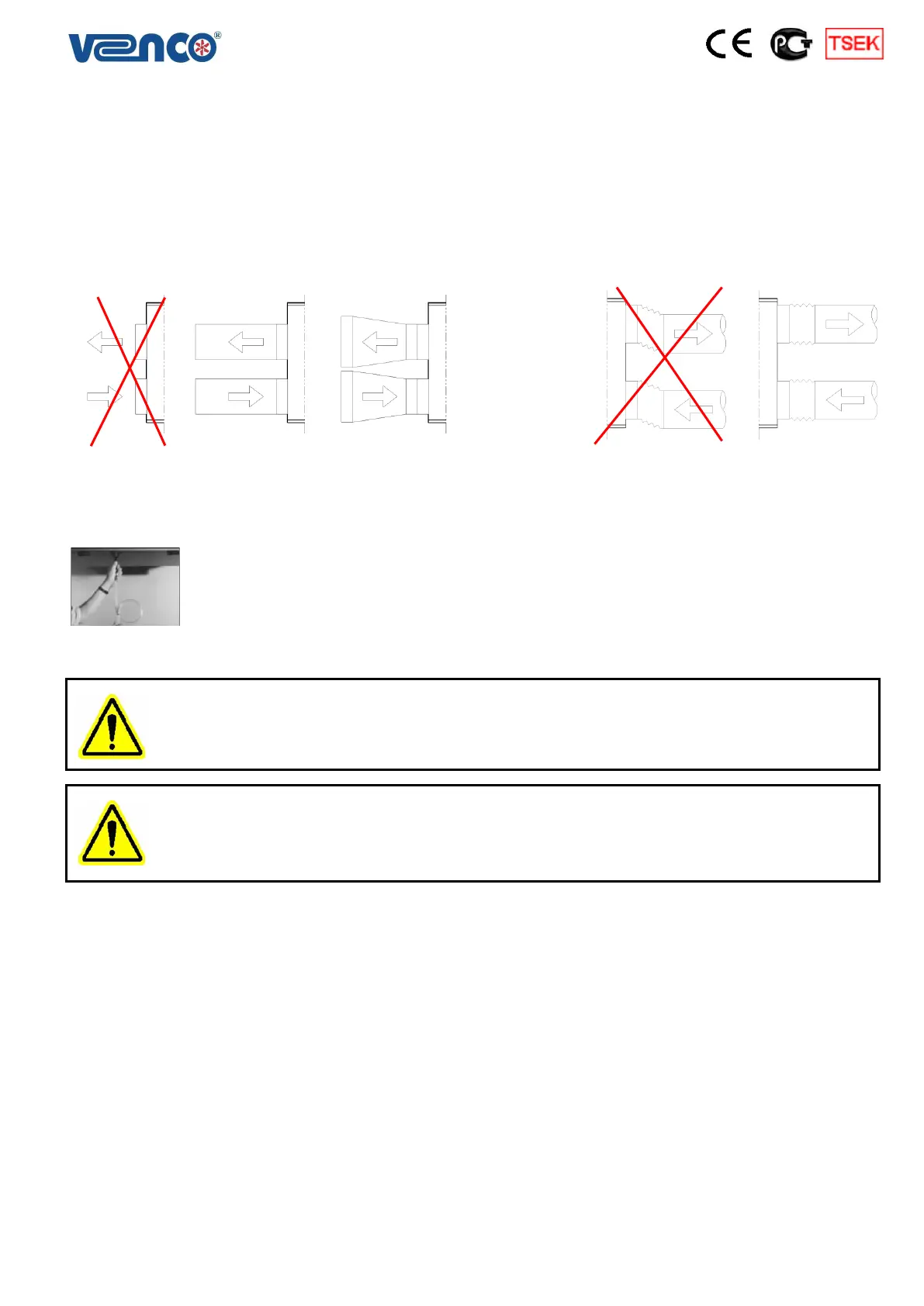
2.1. Duct Connections
Return air, fresh air, exhaust air and supply air ducts should be fixed (connected) to the unit with flexible
connection. Required leak-proofing should be obtained in order to ensure desirable air flow. Having improper
(bad) unit – duct connections and wrong dimension, shape and duct fragments inside of the connection may
cause a turbinated air flow.
Figure 2.1.1. Free Outlet Figure 2.1.2. Ducted Outlet
2.2. Drain Connections
The pipe coming out of the drain pan should be connected to a U or P shaped flusher pipe
and should be filled with water in order to not to cause air suction as described below.
2.3. Electrical Connections
All electricity connections should be designed and prepared according to EN 60204 – 1 Standards. The
electrical materials, cables and all relevant control and remote control equipment should be chosen and
designed suitable to unit peculiarities and requirements. Electrical wiring diagrams are given in “Installation –
Operation and Maintenance Instructions” 17. Appendix Section
ALL ELECTRICAL CONNECTIONS SHALL BE DONE ACCORDING TO EN 60204-1 BY TRAINNED AND
AUTHORIZED PERSONEL.
ELECTRICAL CONNECTIONS ARE READY FOR PLUG-IN CONNECTION. DO NOT CUT CABLE AND
PREPARE PROPER EQUIPMENT TO CONNECT.
 Loading...