8
MOUNTING THE POWER UNIT
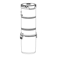
Carefully remove debris pail from power unit. Make sure
bag is properly installed in power unit (550VF1 unit only).
Remove the installation kit and securely reinstall debris pail.
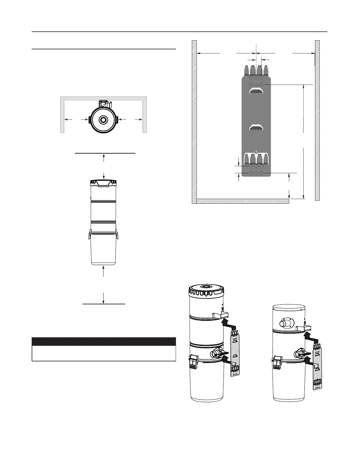
Refer to illustration below to maintain minimum walls and
floor clearance dimensions.
Position and install the wall mounting bracket with the
provided screws. Refer to illustration in the right column for
proper mounting dimensions.
Use the provided mounting screws to secure the mounting
bracket on the wall through upper and lower mounting
holes.
Hang power unit onto wall mounting bracket. Ensure
the back brackets of the power unit are engaged with
corresponding wall bracket fingers (or top fingers and lower
tab for 550VF1 model; see figure below). Pull the power unit
down to secure.
POWER UNIT INSTALLATION (CONT'D)
C
L
3/4” TYP.
32
7
/8”
1” TYP.
45¼”
MIN.
HEIGHT
18 ¹/
8”18 ¹/8”
UPPER
MOUNTING
HOLES
LOWER
MOUNTING
HOLES
AD0079A
CAUTION
Ensure to screw the wall mounting bracket directly
to a wall stud for a solid installation.
18” minimum
above floor
12” minimum
from ceiling
12”
minimum
TOP VIEW
FRONT VIEW
MINIMUM CLEARANCE DIMENSIONS
12”
minimum
AD0039A
AD0074
650VF1 AND 700VF1
550VF1