Do you have a question about the Venmar HEPA 4000 and is the answer not in the manual?
| Brand | Venmar |
|---|---|
| Model | HEPA 4000 |
| Category | Air Cleaner |
| Language | English |
Essential safety instructions to prevent injury, electric shock, or fire.
Important cautions for unit operation and maintenance to avoid damage.
Covers Stand Alone and Central Draw Point methods for HRV/HEPA models.
Describes the Stand Alone installation method for various models.
Explains connecting the unit to a forced air system's return.
Discusses geographical considerations for HEPA 4000 unit installation in the USA.
Provides front and top view dimensions for HRV 2500 and HR 2.5 units.
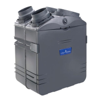
Provides front and top view dimensions for HEPA 3000, HF 3.0, HEPA 4000 units.
Details minimum clearance requirements for unit mounting and door operation.
Check unit and components for shipping damage and completeness.
Lists necessary tools, materials, and specific installation kit numbers.
Guidance on choosing an appropriate location for the unit based on temperature and access.
Identify the most convenient location for mounting the wall control.
Remove cover plate and prepare cable for connection to the control.
Splice and connect control wires (Yellow, Red, Green, Black) to the unit.
Secure the wall control to the wall using anchors and screws.
Keep low voltage wiring away from electrical interference sources.
Open unit door and remove front plate to access internal wiring.
Route cable through unit and connect wires to the appropriate PCB terminals.
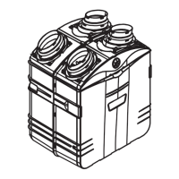
Attach the 8" oval ports and 5" to 6" oval ports to the unit top.
Use chains and springs to hang the unit vertically or horizontally.
Guidelines for planning ductwork, minimizing bends and length.
Procedure for connecting non-insulated ducts for Stand Alone systems.
Instructions for connecting 8" flexible duct to HEPA/HF units and 6" to HRV/HR units.
Identify and attach fresh air and exhaust air ducts to unit ports.
Connect fresh/filtered air ductwork to the forced air unit return.
Trace and cut opening for connecting fresh/filtered air ductwork to return.
Fix duct connector and attach flexible duct to the FRESH AIR TO BUILDING port.
Locate and attach stale air ductwork to the EXHAUST AIR FROM BUILDING port.
Connect insulated flexible ducts to the Tandem® transition (exhaust/fresh air).
Connect insulated flexible ducts to the unit's 5" to 6" oval ports.
Assemble the dual exterior hood parts using screws.
Install the hood at a minimum distance from the ground and other sources.
Cut wall hole, insert Tandem® transition, and connect it to the exterior backplate.
Remove door and core assembly to access and punch out drain fitting holes.
Hand-tighten fittings, cut tubing, and attach to fittings and T-junction.
Form a water trap loop below the T-junction to prevent odor draw-in.
Describes the 3-position main switch (OFF, NORMAL/REMOTE, BOOST).
Identifies the C34 and CMR wall controls for different unit models.
Explains the indicators and functions of the C34/CMR wall control.
Instructions on operating the unit via the wall control (OFF, NORMAL, BOOST, RECIRCULATION).
Steps for biannual maintenance when the Filter Maintenance light flashes.
Instructions for cleaning the core recovery, filter cartridge, and unit interior.
Procedure to reset the filter indicator after maintenance.
Steps for annual maintenance when the Filter Maintenance light stays ON.
Procedure for performing a master reset of the filter indicators.
Solutions for unit not starting at Normal or Boost position.
Solutions for unit not running at Normal speed, but running at Boost.
Solutions for unit not operating as per the selected mode.
Solutions for wall control indicators not working properly or at all.
Solutions for one or two light indicators flashing every second.