TECHNICAL MANUAL
range
CONDENSATE DRAIN PUMP
This pump is used to eliminate the condensation that collects in the tray in installations where there is no self-emptying outlet. The pump comes
with filter to withhold impurities, float with activation contact, suction pipe, pump body complete with control electronics and overheating protection,
wiring.
PUMP Alarm contact normally closed that automatically cuts off the air conditioning system compressor or valve, thermal protection 90° on the
pump coil, electrical connection by plug (delivered with 1 m cable), rubber mounting bracket included..
AVANTAGES Small size, low noise level.
Mains supply 230V - 50Hz 18W
Max. flow rate 20 l/h
Max. suction head 2 m
Max. discharge head 6 m
Alarm contact NC 8 A resistive
Thermal protection (overheat) 90°C
Sound level <34dB(A) a 1 m
Pump dimensions L 66 x I 44 x h 60 mm
Detection unit dimensions L 55 x I 38 x h 32 mm
Weight (including box) ±0.350 kg
Mains supply 230V - 50Hz 18W
Max. flow rate 8 l/h
Max. suction head 1 m
Max. discharge head 6 m
Alarm contact NC 8 A resistive
Thermal protection (overheat) 90°C
Sound level <28dB(A) a 1 m
Pump dimensions L 66 x I 44 x h 60 mm
Detection unit dimensions L 55 x I 38 x h 32 mm
Weight (including box) ±0.350 kg
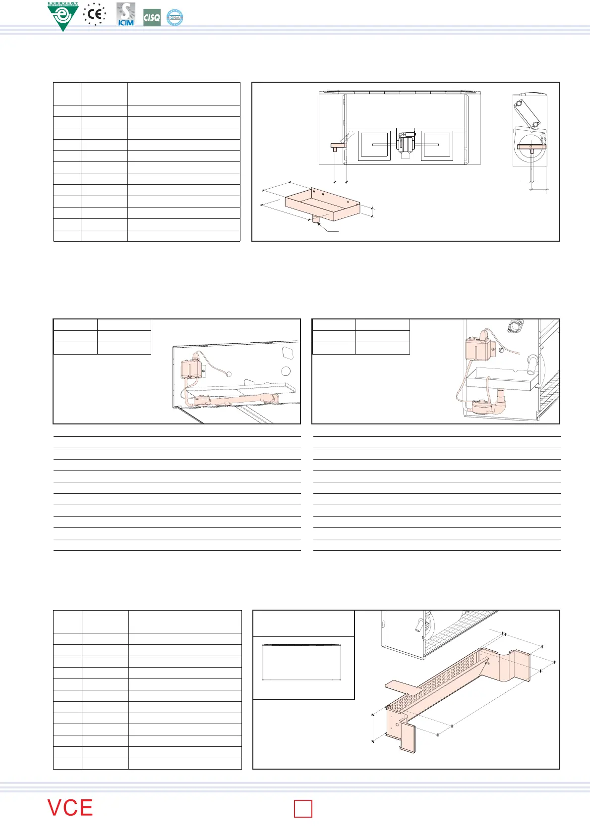
AUXILIARY CONDENSATE COLLECTING TRAY vertical version (INSULATED)
The painted, galvanised sheet metal auxiliary tray is used to collect condensate from the valves and the pipes connecting to the unit. It is suitable
for vertically mounted fan coils.
Y
X
Ø18
A
25
VCE10-60 A0055550000
VCE70-120 A0055550001
MOD. COCE
VCE10-60 A0055550002
VCE70-120 A0055550003
MOD. COCE
VCE10 A0055640049 187 102 93,5 51
VCE20 A0055640049 187 102 93,5 51
VCE30 A0055640049 187 102 93,5 51
VCE40 A0055640049 187 102 93,5 51
VCE50 A0055640049 187 102 93,5 51
VCE60 A0055640049 187 102 93,5 51
VCE70 A0055640049 187 102 93,5 51
VCE80 A0055640049 187 102 93,5 51
VCE90 A0055640049 187 102 93,5 51
VCE100 A0055640050 246 130 126 65
VCE110 A0055640050 246 130 126 65
VCE120 A0055640050 246 130 126 65
MOD. CODE A B X Y
mm mm mm mm
B
Ø 18
FRESH AIR LOUVER
The air lock is made in galvanised sheet metal and may be provided with manual control (placed in line with the same) or with electric servo
control. It is installed at the bottom of the fan coil on the intake line. It may be installed on both the wall-mounted vertical and the ceiling-mounted
horizontal versions. For correct installation, the fan coil must have a pair of feet or intake plinths. Air flow: Internal: 78% - External: 22% - Total:
100%
For VERTICAL
VERSION
VCE10 A0055470001 255 105 105 200
VCE20 A0055470002 455 105 105 200
VCE30 A0055470003 655 105 105 200
VCE40 A0055470003 655 105 105 200
VCE50 A0055470004 855 105 105 200
VCE60 A0055470004 855 105 105 200
VCE70 A0055470004 855 105 105 200
VCE80 A0055470005 1.055 105 105 200
VCE90 A0055470005 1.055 105 105 200
VCE100 A0055470006 1.180 140 140 230
VCE110 A0055470007 1.480 140 140 230
VCE120 A0055470007 1.480 140 140 230
MOD. CODE L A B C
mm mm mm mm
For models VCE1x÷VCE6x For models VCE7x÷VCE12x
Version for
HORIZONTAL
FAN-COIL
Version for
VERTICAL
FAN-COIL
VCEx0
C
14
B
L
A
130
ISO 9001:2000 - Cert. n. 1368/1
32
 Loading...