Do you have a question about the Vents TT 125 and is the answer not in the manual?
Identifies specific terminals like L1, L2, QF, S, ST, and X for fan wiring.
Fan switches to max speed when room temp exceeds set point; operates at set speed when temp drops.
Fan switches to max speed when room temp exceeds set point; uses a 5-min countdown before switching to set speed.
Fan switches to max speed when indoor temp exceeds set point; turns off when temp drops 2°C below set point.
Features a speed controller for on/off and smooth airflow adjustment from minimum to maximum.
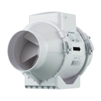
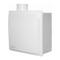
This document serves as a user's manual for the VENTS TT series of centrifugal inline fans, providing essential information for technical, maintenance, and operating staff. It covers the purpose, operating principles, design, installation, and various modifications of the TT unit.
The VENTS TT centrifugal inline fan is designed for both supply and exhaust ventilation in various premises. It functions as an axial mixed-flow fan, ensuring efficient air movement within a ventilation system. The fans are available in different sizes, with models for 100, 125, 150, and 160 mm air ducts featuring a two-speed motor, while larger models for 250 and 315 mm air ducts are equipped with a single-speed motor. Some units for 100, 125, 150, and 160 mm air ducts also come with a two-speed motor.
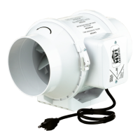
The fan's operation is rated for continuous use and is designed for connection to single-phase AC 220-240 V/50 Hz or 220 V/60 Hz power mains. It has an ingress protection rating of IPX4 against hazardous parts and water ingress, and is classified as a Class II electrical appliance. The fan is suitable for operation in ambient air temperatures ranging from +1 °C to +40 °C. The transported air temperature range varies depending on the model, from -25...+40 °C for TT 100/125 to -25...+60 °C for TT 125S/150/160/250/315, and -25...+40 °C for 220/60 V/Hz power supply.
Various modifications of the TT fan offer enhanced control and functionality:
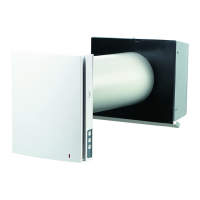
Installation of the fan can be horizontal or vertical, on the floor, wall, or ceiling. It can be installed independently or as part of a series or parallel connection. For optimal performance, a 1 m long air duct is recommended on the intake spigot side for horizontal installations, and a ventilation hood for vertical installations. The exhaust spigot must always be connected to an air duct.
The fan's rotation speed can be controlled by voltage or through thyristor controllers, which are purchased separately. When adjusting voltage, it's crucial to ensure there's no unusual noise or vibration at reduced motor speed, as motor current might exceed the rated current during voltage regulation. The fan is equipped with a thermal switch without self-reset. In case of overheating, the power supply must be switched off to reset the thermal relay, and the cause of overheating must be identified and eliminated. For TT 100 and TT 125 models, the thermal switch cannot be reset, requiring fan replacement in case of overheating.
For models with a timer (TT XXX T), the fan starts when an external switch provides a control signal (e.g., turning on a light). After the control signal is removed, the fan continues to run for a set time, adjustable from 2 to 30 minutes using a control knob. A plastic screwdriver, included in the delivery set, must be used for this adjustment to avoid damaging the circuit board, as the timer circuit is under mains voltage.
Models with electronic TSC control units (TT XXX U/U1/U2(n)) feature two control knobs on the terminal box cover: one for setting fan speed and another for setting the thermostat set point. An LED light on the fan casing indicates when the air temperature exceeds the set point. These models offer automatic speed control based on air temperature, with different logic for U(n), U1(n), and U2(n) variants, including timer-based or direct on/off switching.
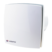
The TT XXX P fan includes an integrated smooth speed controller, allowing users to switch the fan on/off and adjust the air flow smoothly from minimum to maximum.
Regular maintenance is crucial for the fan's longevity and efficient operation. The fan surfaces should be cleaned of dirt and dust every six months. Before any maintenance, the fan must be disconnected from the power supply. For cleaning, a soft cloth or a brush wetted in a mild detergent solution should be used. It is important to avoid water dripping on the electrical components. After cleaning, the fan surfaces must be wiped dry.
Troubleshooting guidance is provided for common issues:
The product must be disposed of separately at the end of its service life and not as unsorted domestic waste.
The manufacturer provides a 24-month warranty from the retail sale date, provided the user adheres to transportation, storage, installation, and operation regulations. Warranty repair covers faults due to manufacturing defects. However, it does not include routine technical maintenance, unit installation/dismantling, or unit setup. To claim warranty service, the user must present the unit, the user's manual with a purchase date stamp, and payment paperwork. The warranty is voided by external damage, unauthorized modifications, misuse, violation of installation or control regulations, incorrect power supply connection, voltage surges, unauthorized repairs, expired warranty, or failure to perform timely technical maintenance.
| Diameter | 125 mm |
|---|---|
| Speed | 2300 RPM |
| Voltage | 220-240 V |
| Current | 0.26 A |
| Type | Inline fan |