This document serves as a user's manual for the D/D1 series of axial fans, providing comprehensive information for technical, maintenance, and operating staff. It covers the fan's purpose, operating principles, design, installation, and maintenance procedures. The manual emphasizes the importance of adhering to all local and national construction, electrical, and technical norms and standards during installation and operation.
Function Description
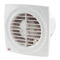
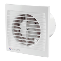
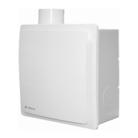
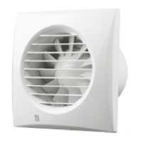
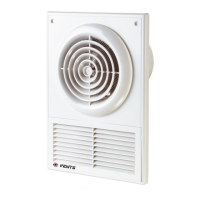
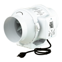
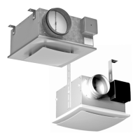
The D/D1 axial fan is designed for exhaust ventilation in small and medium-sized utility spaces. It is suitable for connection to round air ducts of varying diameters, specifically Ø 100, 120, 125, and 150 mm, depending on the specific model. The fan operates on single-phase AC power mains, with power parameters detailed on the unit's packaging and/or casing label.
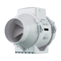
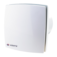
The fan series offers several modifications and basic options to cater to different user needs. Motor modifications include a basic motor, a motor on ball bearings (L option), and a high-powered "Turbo" motor. Additional modifications include non-return valves (K and K1 options). Basic options enhance usability and control, such as a pull cord switch (V), a turn-off delay timer (T), a combination of a turn-off delay timer and a pull cord switch (VT), a humidity sensor (TH), and a combination of a pull cord switch and a humidity sensor (VTH).
The electronic system operation algorithm varies based on the fan model. For "T" model fans equipped with a timer, activation occurs by applying control voltage to the input terminal LT via an external switch, such as an indoor light switch. Once the control voltage is off, the fan continues to operate for a set period, adjustable from 2 to 30 minutes. For "VT" models, the fan can be turned on or off using an internal cord switch. Fans with a timer and a humidity sensor ("TH" models) activate either when control voltage is supplied to the LT terminal or when the indoor humidity level "H" exceeds a pre-set point, adjustable from approximately 60% to 90%. After the control voltage is removed or the humidity level decreases, the fan continues to run for the duration set by the turn-off delay timer. The turn-off delay time and humidity set point are adjusted using control knobs, with a specially designed plastic screwdriver provided for these adjustments to prevent damage to the circuit board.
Usage Features
The D/D1 fan is designed for both wall and ceiling mounting. Wall mounting is suitable for models with motors on both ball and slide bearings, while ceiling mounting is exclusively for models with motors on ball bearings (L option). The fan can facilitate direct outdoor air exhaust through a round duct or a duct system.
When installing the fan for direct air discharge outdoors through a wall, it is crucial to install a ventilation grille with louvre shutters or a ventilation hood on the exterior. This prevents rain, snow, leaves, and other debris from entering the duct. To minimize condensate formation in the duct, the space between the wall opening and the duct must be insulated. The air duct should be installed with a minimum downward slope of 1-2° towards the outer wall to ensure proper condensate removal. For duct systems, the total length should not exceed 5 meters and should have no more than two bends. Vertical air discharge upwards is not permitted during ceiling installation, even with a protective outer hood on the roof. For ceiling mounting with air discharge to the roof, the duct system must incorporate a condensate drain, which is not included in the delivery set and must be ordered separately.
The unit has a protection rating of IP34 against access to hazardous parts and water ingress, making it suitable for installation in zone 2 according to IEC 60364-7-701:2019. It must be installed at a minimum distance of 2.3 meters from the floor. The fan is rated for operation in ambient temperatures ranging from +1 °C to +40 °C. Operating the fan outside this specified temperature range is prohibited. The unit is rated as Class II, 120 V, 60 Hz.
Before installation, users must inspect the fan for any visible damage to the impeller, casing, or grille. The casing internals must be free of any foreign objects that could damage the impeller blades. During mounting, it is essential to avoid compressing the casing, as deformation can lead to motor jam and excessive noise. The fan is mounted using four dowels and screws provided in the delivery set, which are suitable for concrete and brick walls. For other wall materials like drywall or wood, appropriate fasteners must be purchased separately.
The power cable should only be routed through the hole provided by the manufacturer in the casing. Drilling new holes for the power cable is not permitted and will void the warranty. Wires should be stripped of insulation by a maximum of 8 mm. After installation, the user's manual should be passed to the end user for reference.
Maintenance Features
Regular technical maintenance is crucial for the fan's durable operation and is recommended at least once every six months. The maintenance steps are straightforward:
- Disconnect from power supply: Before any maintenance, the fan must be disconnected from the power supply to prevent accidental activation. Measures should be taken to avoid unauthorized power supply connection.
- Remove panels: The decorative and front panels should be removed.
- Clean the fan: The fan should be cleaned with a soft, dry cloth or a brush.
- Wash front panel: The front panel can be washed under running water.
- Dry surfaces: All fan surfaces must be wiped dry.
- Reattach front panel: The front panel should be securely reattached to the fan.
- Reconnect power supply: Finally, the power supply can be reconnected.
A critical warning during maintenance is to prevent water or any liquid from coming into contact with the electrical components.
The manual also provides troubleshooting guidance for common issues. If the fan does not rotate or respond to controls when connected to power mains, the first step is to check the power supply line connection. If the connection is correct, an internal connection fault might be present, requiring contact with the seller. For low air flow, the ventilation system or the impeller might be clogged, necessitating cleaning of either component. If the fan exhibits noise or vibration, it could be due to improper securing or mounting, which requires troubleshooting the installation. A clogged ventilation system can also cause noise and vibration, in which case cleaning the system is recommended.
For storage and transportation, the unit should be kept in its original packaging in a dry, closed, and ventilated area with a temperature range of +5 °C to +40 °C and relative humidity up to 70%. The storage environment must be free of aggressive vapors and chemical mixtures that could cause corrosion, insulation damage, or sealing deformation. Appropriate hoist machinery should be used for handling to prevent damage. The unit must be transported in its original packaging, protected from precipitation and mechanical damage, and only in the working position. Sharp blows, scratches, or rough handling during loading and unloading should be avoided. If the unit has been transported at low temperatures, it must be allowed to warm up at operating temperature for at least 3-4 hours before initial power-up.