Do you have a question about the Vents VKDV-K2 Series and is the answer not in the manual?
Ensures qualified electricians, pre-checks, correct mounting, mains connection, and power-off procedures.
Details pre-mounting checks including manual review, damage inspection, and impeller rotation check.
Covers fan mounting, duct connection, fastening, post-installation checks, fan components, and motor specifications.
Highlights safety rules for disconnection, tampering, mains connection details, and wiring.
Covers responsibility, in-rush current warning, post-start checks, rotation verification, and energy consumption.
Outlines safety rules for disconnection, protection removal, signs, cleaning, start conditions, frequency, and power cuts.
Provides guidance on handling caution, weight, transport, panel protection, lifting accessories, PPE, and suspended load safety.
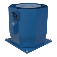
The VKDV-K2 is a series of roof-mounted centrifugal smoke extraction fans designed for a wide range of industrial, public, residential, and administrative premises. Its primary function is the forced removal of smoke and heated gases during a fire, simultaneously extracting heat generated by the fire from the affected area. This helps protect building structures and equipment from high-temperature exposure, prevents the spread of fire to neighboring premises, and removes combustion gases from the serviced space.
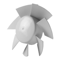
The VKDV-K2 fan operates by drawing in smoke and hot air mixtures and discharging them vertically. It is capable of handling smoke and air mixtures with temperatures up to +600 °C for 60 minutes, making it suitable for critical fire safety applications. The fan's design incorporates an impeller with backward curved blades, which is driven by an electric motor housed within an insulated cover. The entire assembly is mounted on a powder-coated welded body with an insulated cover and a galvanized steel outer casing, ensuring durability and performance in demanding conditions.
The fan's core components include a welded support panel to which the electric motor (with its insulated cover), the terminal box (located on the outer casing), and the impeller (inside the support panel) are attached. The motor and impeller are rigidly fixed to the support panel, ensuring stable operation. Standard fan models are equipped with three-phase electric motors rated for 400 V, 50 Hz, with an IP55 protection class and F (IEC) insulation class.
The VKDV-K2 fan is designed for vertical installation on a concrete or steel base plate, which should be at least 250 mm high to account for potential precipitation levels. It is crucial to install the fan on a building roof, away from potential fire areas, and to ensure that the roof frameworks provide sufficient rigidity to support the unit. Several fans can be installed close to each other on the same roof if required.
Before installation, users must carefully read the user's manual, check for any mechanical damages from transportation, and manually verify that the impeller rotates smoothly. It's also important to ensure there is no condensate on the motor and to check the electrical resistance of insulation between the motor windings and between each winding and the motor casing.
During mounting, the side shields should be removed, and the fan fixed to the mounting frame using four anchor bolts at the frame corners. Care must be taken to avoid compressing or deforming the casing, as this could lead to motor jam and excessive noise. The fan must have free and unhampered air extraction. If a mounting frame is included (available separately), it should be installed true-vertical in a prepared opening on a load-carrying roof section. The opening size must allow for free passage of air ducts with connecting flanges according to DIN 24154 Series 3. The mounting frame should be fixed to the roof surface in compliance with applicable construction norms.
It is recommended to attach the backdraft damper or the first air duct section directly to the fan before installation. Additional fixing of air ducts to building structures is necessary to prevent load transfer from the ducts to the fan. It is critical not to place the fan directly on the air duct during mounting to avoid deformation. Fastening the fan to the mounting frame is done with appropriately sized bolts and washers. After installation, ensure the fan impeller rotates freely.
Connection to the power mains must be performed by qualified electricians with a work permit for electrical units up to 1000 V. A disconnecting device, integrated into the fixed wiring system, must be used, providing full disconnection under overvoltage category III conditions. The connection should use durable, insulated, and heat-resistant conductors, with the wire cross-section selected based on maximum load current, conductor temperature, insulation type, length, and installation method. The fan's electrical parameters are detailed on its label. The fan motor is not equipped with integrated thermal protection, so this must be considered when selecting a starter or closing relay.
During commissioning, it is essential to ensure the fan impeller rotates in the direction marked by the arrow on the fan casing. If necessary, the rotation direction can be changed by altering the phase sequence on the electric motor terminals for three-phase motors or by rewiring according to the diagram for single-phase motors. The organization responsible for commissioning is also responsible for proper motor phasing and starting pattern selection.
The fan's in-rush currents may exceed rated values several times during startup. Various starting methods are available: direct-on-line (DOL), soft starter (SS), or frequency converter (FC). DOL starting, while simple and low-cost, can cause high in-rush currents and mechanical shock, making it suitable only for low-power motors or mechanisms that don't require gradual speed build-up. Soft starters gradually increase voltage, limiting in-rush current and regulating torque, ideal for turbomachinery like fans. Frequency converters raise the frequency from 0 Hz, providing nominal torque at rated current, suitable for high-inertia loads, limited-capacity power supplies, and optimizing power consumption.
After starting, verify that the electric motor rotates without undue vibration or abnormal noise. Check that the fan's energy consumption matches the nameplate value and monitor for overheating. The phase current should be checked once the fan reaches rated operating conditions. Avoid switching the fan on and off repeatedly without pauses, as this can damage the winding or insulation due to overheating.
Technical maintenance and repair of the fan should only commence after it has been disconnected from the power mains and all rotating parts have come to a complete standstill. A prohibitory sign, "DO NOT SWITCH ON! MEN AT WORK!", should be displayed on the fan starting panel. Maintenance includes periodic cleaning of accumulated dust and dirt from the surfaces. It is recommended to perform technical maintenance at least once a year.
During maintenance, check the grounding screw terminals and electric connectors for proper tightness and tighten them if necessary. The fastening screws and the bolt connecting the motor shaft to the hub should also be checked and tightened. The fan impeller should be inspected for contamination and cleaned as needed, which may require removing the outer lining segment. It is crucial to avoid liquid spills on the motor and to refrain from using aggressive solvents or sharp objects for cleaning.
If the fan fails to start, check the power supply and electrical connections. If the motor is jammed, inspect the impeller for seizure; if the impeller is fine, the electric motor may need replacement. If the switching equipment activates upon startup, check for short circuits in the fan or electrical circuit, excessive current consumption, or an improper starting method. If the installed switching equipment is of poor quality or inadequate for the fan's rated values, it should be replaced with a suitable unit from a reputable manufacturer.
If the fan supplies more or less air than expected, re-evaluate network resistance, check for clogged air ducts, or consider if the fan selection or ventilation network calculations were incorrect. If the impeller rotates in the wrong direction, change the phase sequence. Air leaks in duct connections should be sealed, and any foreign objects or debris in the impeller or air ducts should be removed.
Excessive noise or vibration can indicate loose screw connections, a lack of flexible joints between the fan and ventilation network, loose connections of valves and dampers, or contamination in the impeller or air ducts. Worn bearings or an unstable power supply can also cause noise and vibration, requiring bearing replacement or a check of power supply parameters.
For storage, the unit should be kept in its original packaging in a dry, closed, ventilated premise with temperatures between +5 °C and +40 °C and relative humidity up to 70%. The storage environment must not contain aggressive vapors or chemicals that could cause corrosion or damage insulation and seals. Suitable hoist machinery should be used for handling and storage to prevent damage. The unit must be transported in its working position, avoiding sharp blows, scratches, or rough handling. If stored for longer than 3 months, the impeller must be turned regularly by hand to prevent damage. Before initial power-up after transportation at low temperatures, allow the unit to warm to operating temperature for at least 3-4 hours.
When loading, unloading, or installing, always consider the unit's weight and the handling equipment's capacity. Transport the fan using appropriate means like a crane, lifting beam, or forklift, ensuring side panels are protected. Select lifting accessories of sufficient length for even load distribution. Wear protective gloves and safety shoes, and avoid mechanical blows. Never stand underneath a suspended fan. Depending on its size, VKDV-K2 fans are equipped with eyebolts or lifting lugs for hooking with lifting accessories.
| Series | VKDV-K2 |
|---|---|
| Impeller type | Backward curved |
| Frequency | 50/60 Hz |
| Application | Ventilation systems |
| Mounting | Duct |
| Protection class | IP44 |
| Operating temperature range | +60°C |