Vantage 5000 1.0v-11.2016
1. Introduction
The Vantage 5000 can be programmed by the user to dene the relationship between the general purpose outputs pins, 5,
6, 7 & 8, available on the 25 WAY Remote I/O Connector, to select pump functionality status. These selectable outputs are
optically isolated and therefore the Input/Output (I/O) port must be powered from either a local i.e. the Vantage 5000, or a
remote, nominal 24V DC power source.
2. Powering the Input/Output Port
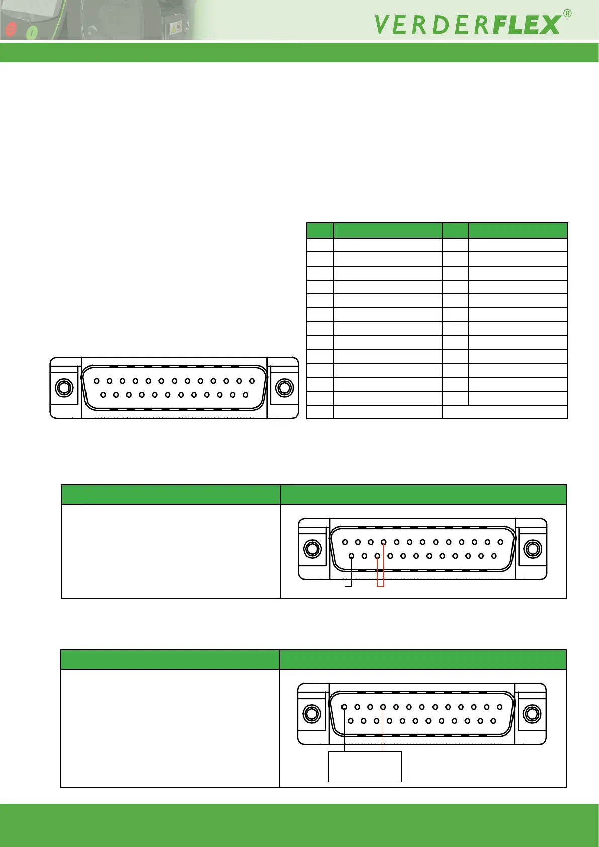
The following images show the Vantage 5000 25 WAY Remote I/O Connector, positioned at the rear of the unit, and the
associated pin out assignment and description table:
2.1 Wiring for Voltage Provided by Pump
2.2 Wiring for Remote Voltage Supply
3 | Page
PIN Description PIN Description
1 Manual/Auto 14 Start
2 Stop 15 Product Source Empty
3 Product Destination Full 16 Direction Input
4 Slave Steps Input 17 Bund Detection
5 General Purpose Output 3 18 Master Steps Output
6 General Purpose Output 4 19 NC (Not Connected)
7 General Purpose Output 2 20 0-10V Output
8 General Purpose Output 1 21 4-20mA Output
9 4-20mA Input 22 0-10V Input
10 Remote I/O +24V 23 +24V Pump Supply
11 +10V Analogue Supply 24 NC (Not Connected)
12 0V Analogue Supply 25 0V Pump Supply
13 Remote I/O 0V
Figure 1 25 WAY Remote I/O Connector - Diagram & Description of PINs
13 12 11 10 9 8 7 6 5 4 3 2 1
25 24 23 22 21 20 19 18 17 16 15 14
Description Wiring Diagrams
This is achieved by linking pin 25 (0V Pump Supply)
to pin 13 (remote I/O 0V) and similarly linking pin
23 (+24V Pump Supply) to pin 10 (Remote I/O
+24V). The user should be aware that when using
local voltage sourcing all of the advantages of I/O
isolation are no longer valid.
13 12 11 10 9 8 7 6 5 4 3 2 1
25 24 23 22 21 20 19 18 17 16 15 14
Description Wiring Diagrams
This is achieved by attaching an external 24V DC
supply the positive line of which is connected
to pin 10 (Remote I/O +24V) and the negative is
connected to pin 13 (Remote I/O 0V). This method
of connection ensures that the vantage 5000 is
electrically isolated from any control and feedback
functionality.
24V DC Power Supply
+24V0V
13 12 11 10 9 8 7 6 5 4 3 2 1
25 24 23 22 21 20 19 18 17 16 15 14
Figure 2 Local Power, I/O Not Isolated
Figure 3 Remote Power, I/O Isolated