The pump should be mounted in a vertical position.
In permanent installations, the pump should be
attached to plant piping using a flexible coupling
on both the intake and
discharge connections
to reduce vibration to
the pump and piping. To
further reduce vibration,
a surge suppressor next
to the pump may
be used.
Suction pipe size should
be at least the same
diameter as the inlet
connection size, even
larger if highly viscous
fluid is to be pumped.
If suction hose is used,
it must be of a non-
collapsible reinforced
type. Discharge piping
should be of at least the
same diameter as the
discharge connection.
It is critical, especially on the suction side of the
pump, that all fittings and connections are air tight
or pumping efficiency will be reduced and priming
will be difficult.
Make certain the air supply line and connections
and compressor are capable of supplying the
required pressure and volume of air to operate the
pump at the desired flow rate. The quality of the
compressed air source should be considered.
Air that is contaminated with moisture and dirt may
result in erratic pump performance and increased
maintenance cost as well as frequent process “down
time” when the pump fails to operate properly.
The pump is powered by compressed air.
Compressed air is directed to the pump air chamber
by the main air valve. The compressed air is
separated from the
fluid by a membrane
called a diaphragm.
The diaphragm in turn
applies pressure on
the fluid and forces it
out of the pump
discharge. While this is
occurring, the opposite
air chamber is de-
pressurized and ex-
hausted to atmosphere
and fluid is drawn into
the pump suction.
The cycle again repeats,
thus creating a constant
reciprocating action
which maintains flow
through the pump.
The flow is always in
through the bottom
suction connection
and out through the top discharge connection. Since
the air pressure acts directly on the diaphragms, the
pressure applied to the fluid roughly approximates
the air supply pressure supplied to the main air valve.
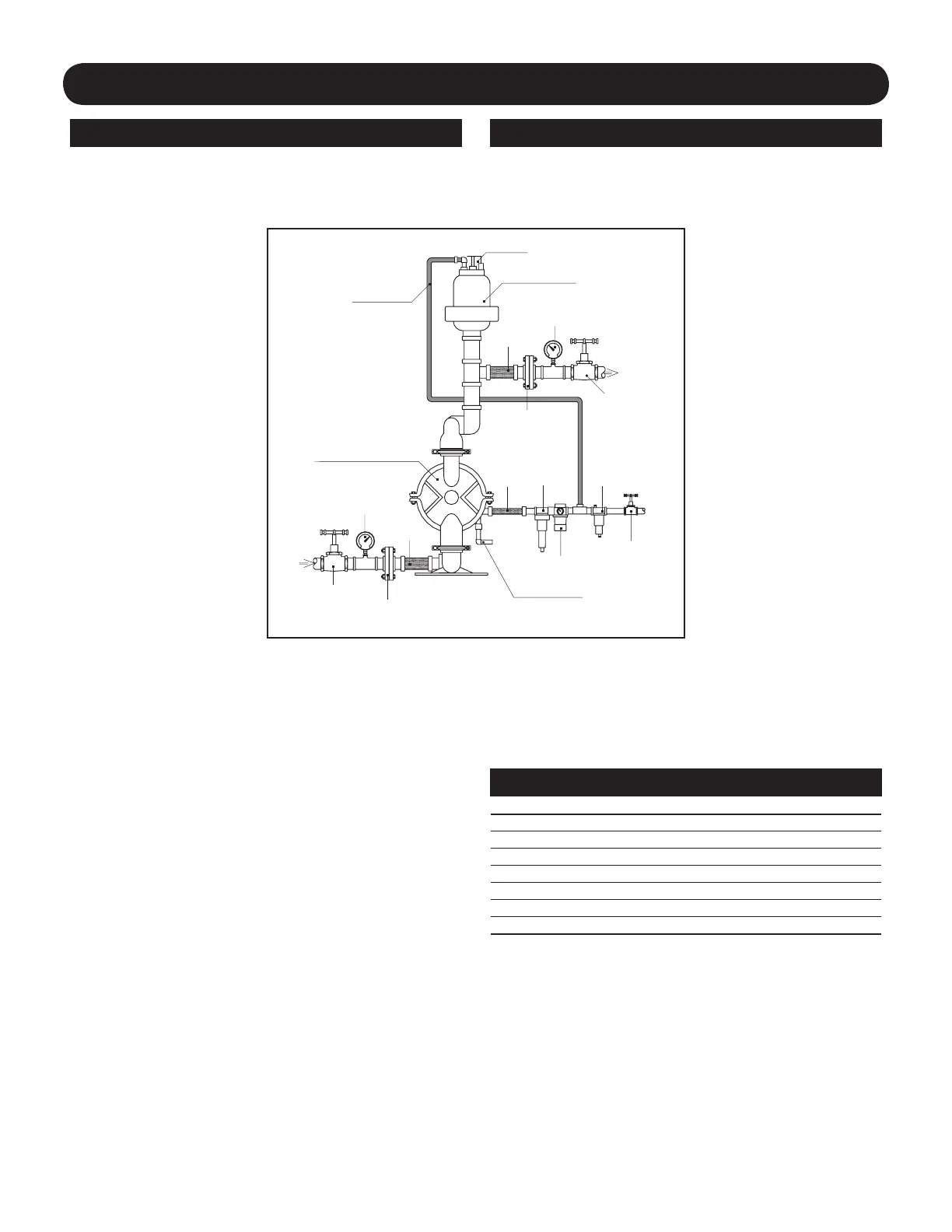
INSTALLATION, OPERATION & MAINTENANCE
Installation Pump Operation
Shut Off Valve
Air Stop Valve/
Needle Valve
Filter
Separator
Pressure-reducing
Valve
Fluid
Inlet
Discharge Pressure
Gauge
Manometer
Shut Off Valve
Air Connection
Fluid
Discharge
AODD PUMP
Air Exhaust
Air Exhaust Muffler
Pulsation Dampener
Union or Pipe Flange
Connection
Union or Pipe Flange
Connection
Flexible
Connection
Flexible
Connection
Flexible
Connection
Pump Size Minimum Air Line Size Minimum Suction Line Size
1/4" 1/4" 1/4"
3/8" 1/4" 3/8"
1/2" 1/2" 1/2"
1" 1/2" 1"
1-1/2" 1/2" 1-1/2"
2" 1/2" 2"
3" 3/4" 3"
Recommended Piping Connections