4-5
39026-03 02/17VERSALIFT VST-8000/8500/9000/9500-I
OPERATION
boom interlock, and tool power. Ground controls
are usually mounted on panels in the rear bumper
of the truck or below the deck. Descriptions and
operating procedures for these controls are given
in the following text.
OUTRIGGER OPERATION - The outriggers should
always be extended to provide stability for the aerial
lift. The outrigger controls consist of a control
selector and a control valve as shown below in
Figure 4.2.
CONTROL SELECTOR AND OUTRIGGER/BOOM
INTERLOCK - The outrigger/boom interlock is
a feature designed to prevent the lift from being
operated until the outriggers are properly extended.
The interlock also prevents the outriggers from being
retracted before the lift is properly stored. This
option is particularly useful in keeping unauthorized
personnel from operating the outriggers while an
operator is working aloft.
Note: The operation of an outrigger interlocking
device(s) does not assure aerial device stability. It
serves only to remind the operator that the outriggers
have not been deployed.
The controls for operating the outrigger/boom
interlock include a detented control selector and a
control valve. These controls are usually mounted in
the ground control panel similar to the arrangement
shown in Figure 4.2 below. ANSI A92.2 standards
require that the outrigger control valve be located
where the operator can watch each outrigger raise
and lower as the control valve lever is activated.
Ground Control Panel With an Outrigger/Boom
Interlock System
Figure 4.2
Lowering the Outriggers With an Outrigger/Boom
Interlock System: To lower the outriggers select
“ground controls” with the control selector. Then
operate the outriggers as described previously.
Select “lift controls” with the control selector in order
to begin operating the booms.
Retracting the Outriggers With an Outrigger/
Boom Interlock System: The booms must be
stowed before the interlock system will allow the
outriggers to be retracted. Stow the booms as
described in this section, “Storing the Aerial Lift”.
Select “ground controls” with the detented control
selector. Then raise the outriggers as described
previously.
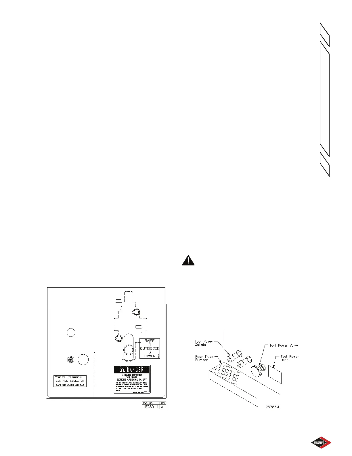
HYDRAULIC TOOL OPERATION AT THE GROUND
(Optional) - Select ground controls at the lift/ground
control selector then connect the hydraulic tool
hoses to the tool power outlets (quick-disconnect
couplings). Activate the tool power valve by pulling
the tool power valve knob “out”. The other aerial lift
controls will not respond while the hydraulic tools are
being operated. To disconnect the hydraulic tools,
the tool power valve must be turned “o” so that the
pressure in the system is relieved. This is done by
pushing the tool power valve knob “in”. Then the tool
hoses can be disconnected safely and easily from
the tool power outlets (quick-disconnect couplings).
The tool power controls are shown in Figure 4.3.
WARNING: FAILURE TO RELIEVE
PRESSURE TO THE TOOL PORTS BEFORE
CONNECTING OR DISCON NECTING THE
HYDRAU LIC TOOL HOSES MAY RESULT IN
A HIGH PRESSURE HYDRAULIC OIL SPRAY.
THIS SPRAY OR MIST CAN PUNCTURE OR
BECOME EMBEDDED BENEATH THE SKIN OR
CONTAMINATE THE EYES. THESE CONDI TIONS
REQUIRE IMMEDIATE MEDICAL ATTEN TION.
Tool Power Controls
Figure 4.3
 Loading...