4-12
39026-03 02/17
VERSALIFT VST-8000/8500/9000/9500-I
OPERATION
ROPE ATTACHMENT ARE NOT DESIGNED FOR
FULL ROPE EXTENSION. THE RECOIL FROM
ROPE DETACHMENT OR FALLING OBJECTS
CAN CAUSE DEATH OR SERIOUS INJURY TO
THE OPERATOR OR GROUND CREW.
HYDRAULIC JIB OPERATION (If Equipped)
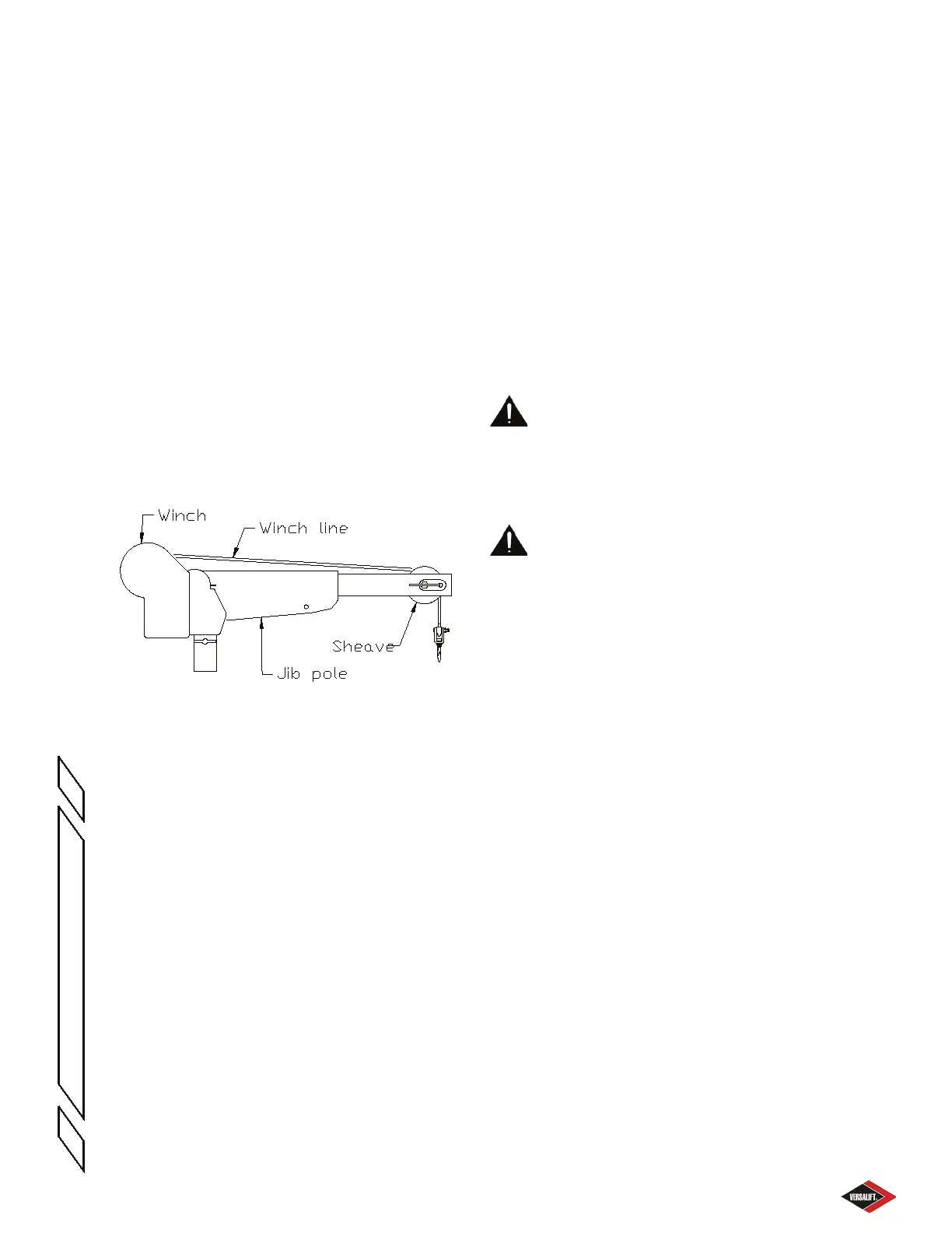
The optional material handling system is designed
to lift loads to the work site at the platform. The
main components of this system are the sheave,
winch line, jib pole, and the winch. The jib pole tilts
and extends hydraulically, and rotates manually.
Although some of the components of the jib and
winch are made from non-conductive materials, they
are not tested or maintained as insulating. Therefore,
the entire jib and winch assembly, including the jib
pole and rope, must be considered conductive and
have no insulating value.
Hydraulic Jib Major Components
Figure 4.8
Hydraulic Tilt, Extend and Winch Operation
-Controls for these functions are located in the upper
control panel mounted to the platform. To operate,
move the appropriate lever in the direction indicated
on the decal. The winch control is also duplicated at
the lower controls for use in case of an emergency.
When operating from the lower controls, the winch
speed will be slower.
Jib Rotation - The jib pole assembly can be rotated
to one of seven dierent positions to accommodate
a load. These load lifting positions are located at
15°, 45° and 75° to either side of the boom. See
Figure 4.7.
To rotate the jib assembly, follow the sequence
below:
1. Remove any load from the jib and winch
assembly. Never attempt to rotate the jib while
under load.
2. Remove the jib rotation lock pin.
3. Rotate the jib to the desired position.
4. Fully replace the lock pin.
JIB CAPACITY DETERMINATION
For 1000 lbs. Jib
The lifting capacity of the material handling system is
conditional and depends on the angle of the jib pole,
the extension of the inner boom, and the angle of
the outer boom. To determine the lifting capacity of
the jib at a particular position, refer to the procedure
and example below. The capacities shown here are
for example only. Refer to the decals on the unit for
the actual lifting capacities.
DANGER: NEVER EXCEED THE MAXIMUM
LIFTING CAPACITY AS SHOWN BY THE MATERIAL
HANDLING LOAD CHART. OVERLOADING
THE LIFT MAY CAUSE EQUIPMENT FAILURE
RESULTING IN DEATH OR SERIOUS INJURY.
DANGER: EXCEEDING THE MAXIMUM
LIFTING CAPACITY OF THE LIFT OR THE JIB
MAY CAUSE EQUIPMENT FAILURE RESULTING
IN DEATH OR SERIOUS INJURY.
Jib Capacity Component Description - The inner
boom is color coded.
VST-8000/8500/9000-I - It is painted white from 0
to 47 inches of extension. From 47 to 132 inches,
the exterior of the inner boom is marked with green
decals. After 132 inches, the exterior of the inner
boom is marked with red decals.
VST-9500-I - It is painted white from 0 to 45 inches
of extension. From 45 to 130 inches, the exterior of
the inner boom is marked with green decals. After
130 inches, the exterior of the inner boom is marked
with red decals.
The inner boom is equipped with a pointer and jib
capacity decal. The pointer responds to gravity, so
as the boom angle changes, the pointer tracks to
dierent areas of the decal. The decal is divided in
to three zones, one white, one green, and one red.
The jib pole is equipped with maximum capacity
decals near the pivot
Procedure to Determine the Jib Capacity:
1. Determine the color of the inner boom where it
exits the outer boom. It will be either red, green
or white.
 Loading...