Do you have a question about the Vertex Standard EVX-534 and is the answer not in the manual?
Instructions for attaching and detaching the battery pack from the radio unit.
Procedure for charging the radio's battery pack using the desktop charger.
How the radio indicates when the battery power is low, typically via LED or icon.
Steps for attaching and detaching the belt clip accessory to the radio.
Guide for installing the microphone/speaker cap to protect the jack.
Initial setup tasks before operating the radio, such as attaching antenna and battery.
Basic steps to turn on and select channels for immediate radio use.
Function to limit transmission length and prevent continuous keying.
Details on customizing and assigning functions to programmable keys on the radio.
Cancels signaling features and controls LED indicator. Icon " " shown when active.
Adjusts privacy settings to enhance security. Selects desired Privacy Code for encryption.
Manually adjusts squelch level. Options: Open, Threshold, Normal, Tight.
Initiates an emergency call for alerting. Displays "- Emergency -" indication.
Monitors multiple channels, stopping on active signals. Can scan digital and analog channels.
Sends call signals like 2-Tone, 5-Tone, MDC1200, or Digital Call. Varies by operating mode.
Allows sending, receiving, editing, and deleting messages between radios.
Locks CH Selector, Programmable keys, and PTT switch to prevent accidental changes.
Allows user to define/configure settings like Squelch, Key lockout, Beep, etc.
| Brand | Vertex Standard |
|---|---|
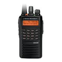
| Model | EVX-534 |
| Category | Two-Way Radio |
| Language | English |