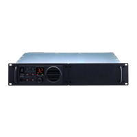
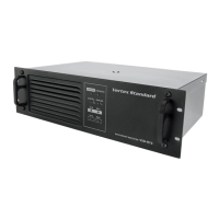
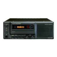
VXR-7000U
K66VXR-7000U_Alignment.doc
r Adjust TC2001 (on the TX unit), if necessary, so that the frequency counter reading is within
±100Hz of the programmed Center channel frequency.
Transmitter parameters (excluding PLL)
r The following transmitter parameters can be adjusted from the computer by utilizing the CE-27
Channel/Alignment Diskette. Refer to the onboard help of the CE-27 Channel/Alignment
Diskette for details.
TX PARAMETERS DATA
TX Power Level (High) 0 (00h) ~ 255 (FFh)
TX Power Level (Low) 0 (00h) ~ 255 (FFh)
Maximum Deviation 0 (00h) ~ 255 (FFh)
CTCSS Deviation 0 (00h) ~ 255 (FFh)
DCS Deviation 0 (00h) ~ 255 (FFh)
Receiver
PLL VCV (Varactor Control Voltage) Check
r Connect the DC voltmeter between the VCV check point (on the RX Unit) and chassis ground.
r Select the High band edge channel, and confirm that the DC voltmeter reading is 4.1•}0.3 VDC.
PLL Reference Frequency Adjustment
r Connect the Frequency counter to J3001 on the RX Unit.
r Select the Center channel, adjust TC3001 (on the RX Unit), if necessary, so that the frequency
counter reading is within ±100Hz of the programmed Center channel frequency.
Receiver parameters (excluding PLL)
r The following receiver parameters can be adjusted from the computer by utilizing the CE-27
Channel/Alignment Diskette. Refer to the onboard help of the CE-27 Channel/Alignment
Diskette for details
RX PARAMETERS DATA
Squelch Threshold Level 0 (00h) ~ 255 (FFh)
Squelch W/N Level 0 (00h) ~ 255 (FFh)
RSSI Threshold Level 0 (00h) ~ 255 (FFh)
RX Tune Level 0 (00h) ~ 255 (FFh)
Repeater Mode
Deviation Adjustment
r First ensure that the “DUPLEX” mode of operation is enabled via CE-27 programming.
r Set the BASE/REPEATER switch on the front panel of the repeater to the “REPEATER” mode
(the REPEATER LED will turn on).
r Inject a signal on the Center channel frequency at a level of 40 dBµ (1 kHz tone @ ±3 kHz
deviation) from the RF Signal Generator into the RX antenna jack, and adjust VR4001 (on the
CNTL Unit) so that the deviation meter reading (TX deviation) is ±3.0 kHz (±0.1 kHz)
deviation.
 Loading...