Do you have a question about the Vertex Standard VXR-9000 and is the answer not in the manual?
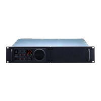
Describes the VXR-9000 repeater, its capabilities, and programming.
Outlines safety warnings and important notices for users.
Details the power switch, main/backup indicators, TX, and BUSY indicators.
Describes the MIC jack, VOL knob, numeric display, and speaker.
Introduces the PF keys and their programmability.
Explains CH DOWN, CH UP, COMPANDER, CTCSS/DCS functions.
Covers CW ID and Two Tone Dec functions.
Details DC Power Save, Encryption, Key Lock, and Monitor functions.
Covers Remote, Repeat, Reset, and Local PTT functions.
Explains Scan, Squelch, Test Tone, and TOT functions.
Covers Transmit, TX Power Mid, and TX Power Low functions.
Describes power terminals, fuses, and antenna jacks.
Details external speaker jack and DSUB 25-pin accessory connector.
Describes GND and +13.6V power supply pins.
Details audio input, control, and output pins.
Covers RSSI and No Connection (N.C.) pins.
Details the eight programmable input/output ports (PIO).
Covers RXD LOW/HIGH and TXD LOW/HIGH data pins.
Describes squelch detection and external PTT pins.
Discusses antenna placement and types for repeater operation.
Advises on rack installation and operating environment.
Details power source specifications and connections.
Explains backup battery connection and behavior.
Lists items included with the repeater.
Lists available optional accessories for purchase.
Provides information on warranty coverage and terms.
| Brand | Vertex Standard |
|---|---|
| Model | VXR-9000 |
| Category | Repeater |
| Language | English |