VXR-9000 FM REPEATER OPERATING MANUAL
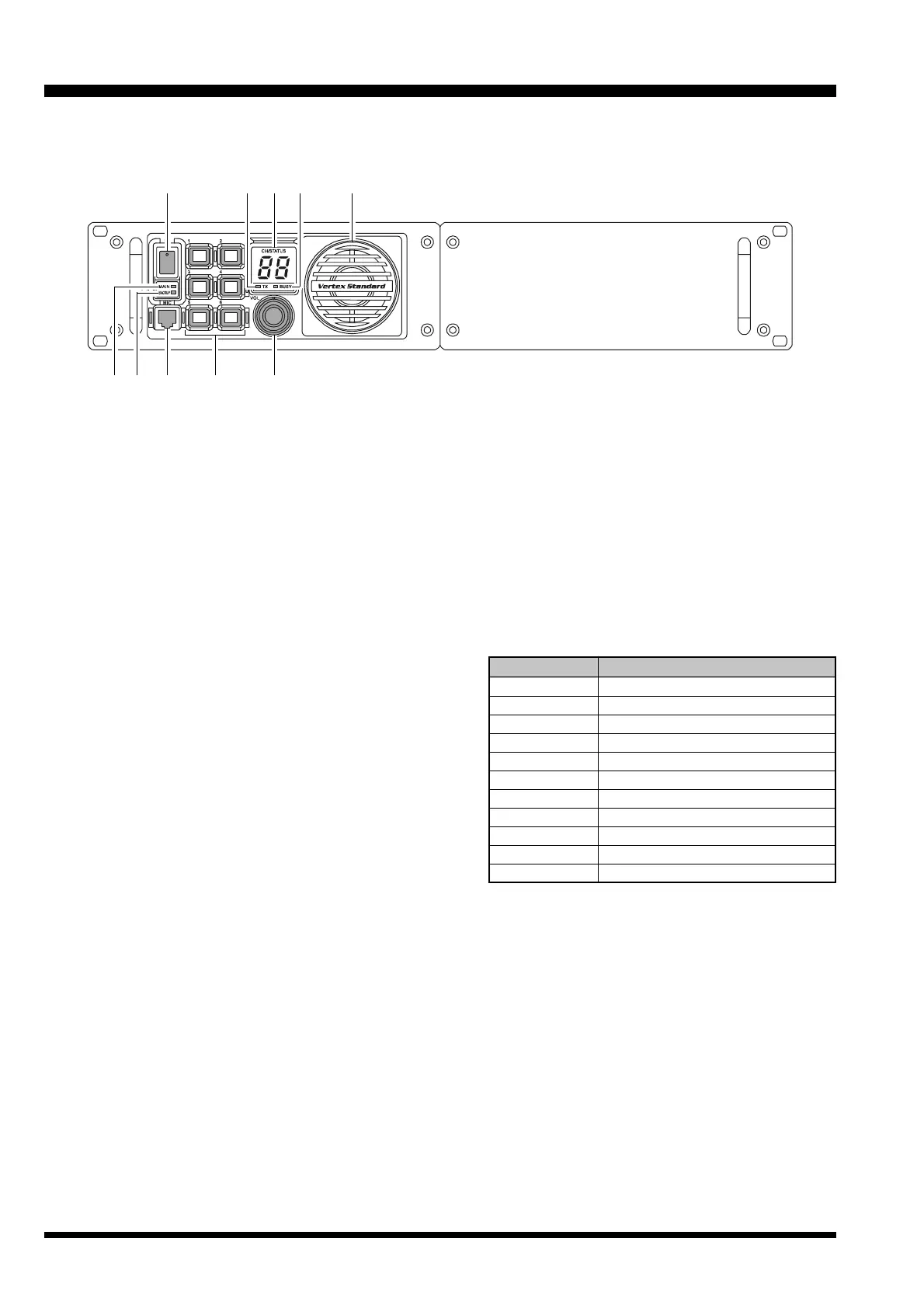
FRONT PANEL CONTROLS & CONNECTORS
POWER
(
O/I
)
Switch
This is the main power switch for the repeater.
Power Indicator
(
MAIN
)
This LED glows green when the main power source
is used.
Power Indicator
(
BACKUP
)
This LED glows red when the backup power source
is used.
MIC Jack
Connect the microphone plug to this jack. This jack
is also used for writing and reading channel fre-
quency or other configurations via the USB Port of
the PC on which the clone editor (CE60) is running.
Programmable Function
(
PF
)
Key
Six pushbuttons on the front panel are program-
mable function (PF) keys, each with an orange indi-
cator inside. Each key can be programmed with two
functions, one for a “long” press and one for a “mo-
mentary” press. The PF key functions may be cus-
tomized, via programming by your VERTEX STAN-
DARD dealer, to meet your communications net-
work requirements. Note that some functions may
require the purchase of optional internal accesso-
ries. The possible PF key features and functions are
explained on the pages to follow.
VOL Knob
This control knob adjusts the output level of the front
speaker and external speaker jack on the back panel.
TX Indicator
This LED glows red when the repeater is transmit-
ting.
Numeric Display
This display consists of two 7-segment LEDs, indi-
cating the channel number during normal operation.
If an abnormal condition arises, an error code will be
displayed:
2
DISPLAY DESCRIPTION
01 - 32 Channel Number
PC Clone Active
UL PLL Unlock
HI High temperature in PA Unit
SC Scan Active
LC Front Panel Keys are Locked
E1 PTT key is Disabled
E2 Cooling Fan is Disabled
E5 Low Voltage in Backup Battery
E7 PA Unit Abnormality
E3, E4, E6, E9 Contact your Dealer
BUSY Indicator
This LED glows green when the receiving channel
is busy.
Speaker
The internal speaker is located here.
 Loading...