EasyManua.ls Logo

Vertex Standard VXR-7000 Service Manual

Vertex Standard VXR-7000
146 pages
To Next Page IconTo Next Page
Page #1 background imageLoading...
Page #1 background image
1VXR-7000 UHF Service Manual
Introduction
This manual provides technical information necessary for servicing the VXR-7000 FM Land Mobile Repeater.
Servicing this equipment requires expertise in handling surface-mount chip components. Attempts by non-qualified
persons to service this equipment may result in permanent damage not covered by the warranty, and may be illegal in
some countries.
Two PCB layout diagrams are provided for each double-sided circuit board in the repeater. Each side of is referred to
by the type of the majority of components installed on that side (“leaded” or “chip-only”). In most cases one side has only
chip components, and the other has either a mixture of both chip and leaded components (trimmers, coils, electrolytic
capacitors, ICs, etc.), or leaded components only.
While we believe the technical information in this manual to be correct, VERTEX STANDARD assumes no liability
for damage that may occur as a result of typographical or other errors that may be present. Your cooperation in pointing
out any inconsistencies in the technical information would be appreciated.
Important Note
After Lot. 78 of this transceiver is assembled using Pb (lead) free solder, based on the RoHS specification.
Only lead-free solder (Alloy Composition: Sn-3.0Ag-0.5Cu) should be used for repairs performed on this apparatus. The
solder stated above utilizes the alloy composition required for compliance with the lead-free specification, and any solder with
the above alloy composition may be used.
Service Manual
VXR-7000 (UHF)
Desktop Repeater
Contents
Operating Manual Reprint.......................... 2
CE27 Programming Software Instruction ............10
Specifications............................................... 16
Exploded View & Miscellaneous Parts... 17
Block Diagram ............................................. 21
Interconnection Diagram........................... 24
Circuit Description .................................... 25
Alignment..................................................... 28
Board Unit (Schematics, Layouts & Parts)
PA Unit (Lot.1-61) .................................................. 33
PA-2 Unit (Lot.62-) .................................................41
TX Unit (Lot.1-59) .................................................. 49
TX-2 Unit (Lot.60-) .................................................57
RX Unit (Lot.1-59) .................................................. 67
RX-2 Unit (Lot.60-) ................................................. 77
CNTL Unit .............................................................. 87
Display Unit .......................................................... 105
Key Unit ................................................................ 113
Filter Unit (50W Type) ........................................ 123
Filter-2 Unit (25W Type) .....................................129
SW Unit (25W Type) ............................................135
VR Unit ..................................................................137
SQL Unit ................................................................ 139
PS Unit ...................................................................141
Vertex Standard LMR, Inc.
©
2015 Vertex Standard LMR, Inc.
E136890N

Other manuals for Vertex Standard VXR-7000

Question and Answer IconNeed help?

Do you have a question about the Vertex Standard VXR-7000 and is the answer not in the manual?

Vertex Standard VXR-7000 Specifications

General IconGeneral
Modulation16K0F3E, 11K0F3E
Operating Temperature-30°C to +60°C
Channel Capacity16
Power Output50 W
Operating Voltage13.8 VDC ± 15%

Summary

Introduction to VXR-7000 Service Manual

Important Safety and Operational Notes

Operating Manual: Controls and Features

Front Panel Controls and Indicators

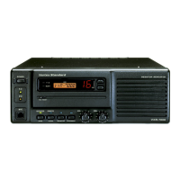
Details the functions of front panel controls, switches, knobs, and indicators.

Rear Panel Connectors and Ports

Describes the purpose and pinouts of all connectors on the rear panel.

ACC Jack Connector Port Details

Explains the pinout and functionality of the DB-25 ACC jack for accessory connections.

LINE Interface Port Details

Details the pinout and functionality of the 8-pin modular LINE interface port.

Installation Procedures

Covers antenna considerations and AC power supply voltage selection.

DC Power Supply Backup

Covers battery backup connection for uninterrupted operation.

Equipment Location Guidelines

Provides recommendations for optimal repeater placement and environment.

AC Mains Wiring Modification Procedure

Provides step-by-step instructions for modifying AC mains voltage wiring.

CE27 Programming Software Operations

Guides on connecting, operating, and programming with the CE27 software.

Specifications

USA (NA) and Except EIA (CE) Models

Lists general, receiver, and transmitter specifications for NA and non-EIA/CE models.

EIA (CE) Model

Lists general, receiver, and transmitter specifications for EIA/CE models.

Exploded Views and Parts Lists

Exploded View & Miscellaneous Parts (Lot. 1~70)

Illustrates the assembly and lists miscellaneous parts for Lot 1-70.

Exploded View & Miscellaneous Parts (Lot.71~164)

Illustrates the assembly and lists miscellaneous parts for Lot 71-164.

Exploded View & Miscellaneous Parts (Lot.165~)

Illustrates the assembly and lists miscellaneous parts for Lot 165 and later.

Diagrams and Descriptions

Block Diagrams

Shows the overall functional blocks and interconnections of the repeater system.

Interconnection Diagram

Details how the internal units of the repeater are interconnected.

Circuit Description

Provides detailed explanations of the operational paths and circuits within the repeater.

Alignment Procedures

Test Equipment and Preparations

Lists necessary test equipment and essential preparation steps for alignment.

Transmitter Alignment

Covers VCV checks, frequency adjustments, and parameter settings for the transmitter.

Receiver Alignment

Covers VCV checks, frequency adjustments, and parameter settings for the receiver.

Mode-Specific Adjustments

Details deviation and audio level adjustments for repeater and base modes.

PA Unit (Lot. 1-61) Information

Circuit Diagrams

Circuit diagrams for PA Unit, Lot. 1-17 and Lot. 18-61.

Parts Layout

Component layout diagrams for PA Unit Side A and Side B.

Parts List

Detailed list of parts for PA Unit, Lot. 1-61.

PA-2 Unit (Lot. 62~) Information

Circuit Diagram

Circuit diagram for PA-2 Unit, Lot. 62~.

Parts Layout

Component layout diagrams for PA-2 Unit Side A and Side B.

Parts List

Detailed list of parts for PA-2 Unit, Lot. 62~.

TX Unit (Lot.1-59) Information

Circuit Diagrams

Circuit diagrams for TX Unit, Lot. 1-59 and Lot. 18-59.

Parts Layout

Component layout diagrams for TX Unit Side A and Side B.

Parts List

Detailed list of parts for TX Unit, Lot.1-59.

TX-2 Unit (Lot. 60~) Information

Circuit Diagram

Circuit diagram for TX-2 Unit, Lot. 60~.

Parts Layout

Component layout diagrams for TX-2 Unit Side A and Side B.

Parts List

Detailed list of parts for TX-2 Unit, Lot. 60~.

RX Unit (Lot.1-59) Information

Circuit Diagrams

Circuit diagrams for RX Unit, Lot. 1-17 and Lot. 18-59.

Parts Layout

Component layout diagrams for RX Unit Side A and Side B.

Parts List

Detailed list of parts for RX Unit, Lot.1-59.

RX-2 Unit (Lot. 60~) Information

Circuit Diagram

Circuit diagram for RX-2 Unit, Lot. 60~.

Parts Layout

Component layout diagrams for RX-2 Unit Side A and Side B.

Parts List

Detailed list of parts for RX-2 Unit, Lot. 60~.

CNTL Unit Information

CNTL Unit Circuit Diagrams

Circuit diagrams for CNTL Unit, Lot. 1-107, Lot. 5-18, Lot. 19~.

CNTL Unit Parts Layout

Component layout diagrams for CNTL Unit Side A and Side B.

CNTL Unit Parts List

Detailed list of parts for CNTL Unit.

Display Unit Information

Display Unit Circuit Diagrams

Circuit diagrams for Display Unit, Lot. 1-107 and Lot. 108-.

Display Unit Parts Layout

Component layout diagrams for Display Unit Side A and Side B.

Display Unit Parts List

Detailed list of parts for Display Unit.

Key Unit Information

Key Unit Circuit Diagrams

Circuit diagrams for Key Unit, Lot. 1-5, Lot. 6-107, Lot. 108-.

Key Unit Parts Layout

Component layout diagrams for Key Unit Side A and Side B.

Key Unit Parts List

Detailed list of parts for Key Unit.

Filter Unit (50W Type) Information

Circuit Diagram

Circuit diagram for the 50W Type Filter Unit.

Parts Layout

Component layout diagrams for Filter Unit Side A and Side B.

Parts List

Detailed list of parts for the 50W Type Filter Unit.

Filter-2 Unit (25W Type) Information

Circuit Diagram

Circuit diagram for the 25W Type Filter-2 Unit.

Parts Layout

Component layout diagrams for Filter-2 Unit Side A and Side B.

Parts List

Detailed list of parts for the 25W Type Filter-2 Unit.

SW Unit (25W Type) Information

Circuit Diagram

Circuit diagram for the SW Unit (25W Type).

Parts Layout

Component layout diagrams for SW Unit Side A and Side B.

VR Unit Information

VR Unit Circuit Diagrams

Circuit diagrams for VR Unit, Lot. 1-107 and Lot. 108-.

VR Unit Parts Layout

Component layout diagrams for VR Unit Side A and Side B.

VR Unit Parts List

Detailed list of parts for VR Unit.

SQL Unit Information

SQL Unit Circuit Diagrams

Circuit diagrams for SQL Unit, Lot. 1-107 and Lot. 108-.

SQL Unit Parts Layout

Component layout diagrams for SQL Unit Side A and Side B.

SQL Unit Parts List

Detailed list of parts for SQL Unit.

PS Unit Information

PS Unit Circuit Diagram

Circuit diagram for the PS Unit.

PS Unit Parts Layout

Component layout diagram for PS Unit Side A.

PS Unit Parts List

Detailed list of parts for the PS Unit.

Related product manuals