29VXR-7000 UHF Service Manual
Alignment
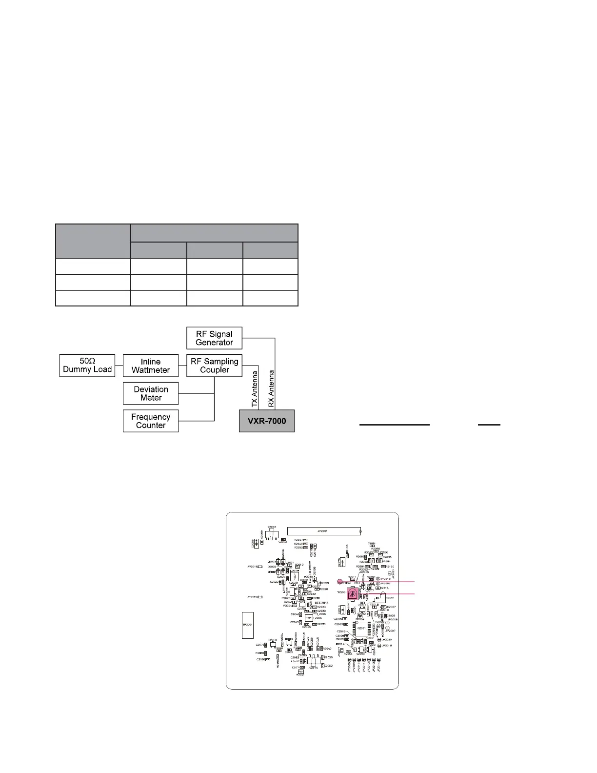
Set up the test equipment as shown below, and apply
AC power to the repeater.
The repeater must be programmed for use in the in-
tended system before alignment is attempted. The frequen-
cy and other parameters are loaded from the file during
the alignment process.
In order to facilitate alignment over the complete
switching range of the equipment it is recommended that
the channel data first be uploaded and then stored to disk.
Channels at the upper, lower and middle band edges should
then be downloaded. The original data can be replaced at
the end of the alignment process.
Channel
Frequency (MHz)
Ver. D Ver. A Ver. BS1
Low band edge 450.000 400.000 420.000
Center 465.000 415.000 435.000
High band edge 480.000 430.000 450.000
Transmitter
Press the BASE/REPEATER switch on the front panel
of the repeater so as to set it to the “BASE” mode if the
REPEATER LED is on. You should see the REPEAT-
ER LED turn off, indicating that the repeater is now in
the “BASE” mode.
PLL VCV (Varactor Control Voltage) Check
Connect the DC voltmeter between the VCV check
point (on the TX Unit) and chassis ground.
Select the Low band edge channel, then key the re-
peater. Confirm that the DC voltmeter reading is 0.6
~ 1.5 VDC (TYP D) or 1.5 ± 0.3 VDC (TYP A) or
1.2 ~ 1.8 VDC (TYP BS1).
Select the High band edge channel, then key the re-
peater. Confirm that the DC voltmeter reading is 3.8
~ 4.5 VDC (TYP D) or 3.6 ± 0.4 VDC (TYP A) or
3.2 ~ 4.0 VDC (TYP BS1).
PLL Reference Frequency Adjustment
Select the Center channel, then key the repeater.
Adjust TC2001 (on the TX unit), if necessary, so
that the frequency counter reading is within ±100Hz
of the programmed Center channel frequency.
Transmitter parameters (excluding PLL)
The following transmitter parameters can be adjust-
ed from the computer by utilizing the CE27 Chan-
nel/Alignment Program. Refer to the onboard help
of the CE27 Channel/Alignment Program for details.
TX Parameters Data
TX Power Level (High) 0 (00h) ~ 255 (FFh)
TX Power Level (Low) 0 (00h) ~ 255 (FFh)
Maximum Deviation 0 (00h) ~ 255 (FFh)
CTCSS Deviation 0 (00h) ~ 255 (FFh)
DCS Deviation 0 (00h) ~ 255 (FFh)
Alignment Setup
TX Unit Alignment Points
VCV Check Point
TC2001
 Loading...