30 VXR-7000 UHF Service Manual
Alignment
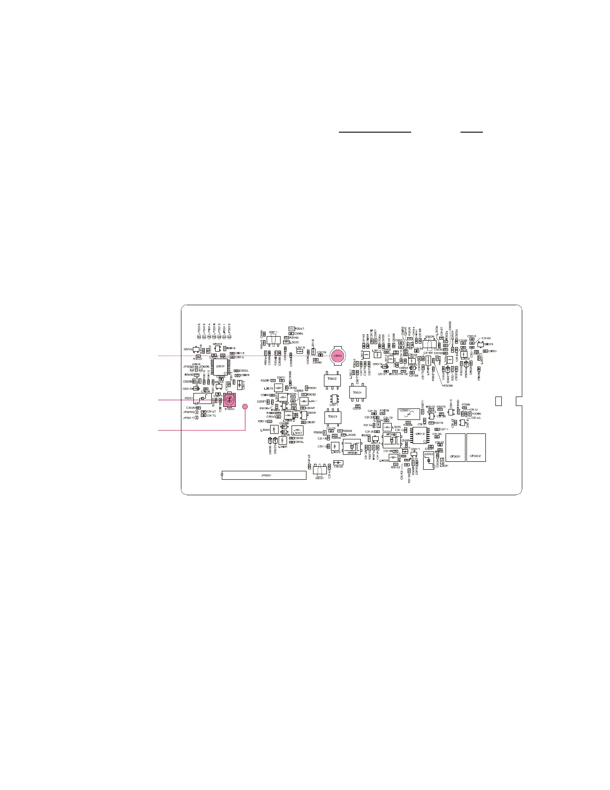
RX Unit Alignment Points
Receiver
PLL VCV (Varactor Control Voltage) Check
Connect the DC voltmeter between the VCV check
point (on the RX Unit) and chassis ground.
Select the Low band edge channel, and confirm that
the DC voltmeter reading is 1.6 ± 0.3 VDC (TYP D)
or 1.3 ± 0.3 VDC (TYP A) or 1.0 ~ 1.9 VDC (TYP
BS1).
Select the High band edge channel, and confirm that
the DC voltmeter reading is 4.5 ± 0.5 VDC (TYP D)
or 4.3 ± 0.5 VDC (TYP A) or 3.3 ~ 4.8 VDC (TYP
BS1).
PLL Reference Frequency Adjustment
Connect the Frequency counter to J3001 on the RX
Unit.
Select the Center channel, adjust TC3001 (on the
RX Unit), if necessary, so that the frequency counter
reading is within ±100 Hz of the programmed Cen-
ter channel frequency.
Receiver parameters (excluding PLL)
The following receiver parameters can be adjusted
from the computer by utilizing the CE27 Channel/
Alignment Program. Refer to the onboard help of the
CE27 Channel/Alignment Program for details.
RX Parameters Data
Squelch Threshold Level 0 (00h) ~ 255 (FFh)
Squelch W/N Level 0 (00h) ~ 255 (FFh)
RSSI Threshold Level 0 (00h) ~ 255 (FFh)
RX Tune Level 0 (00h) ~ 255 (FFh)
VCV Check Point
J3001
TC3001
 Loading...