VXR-9000 FM REPEATER OPERATING MANUAL
Pin 10, 13, 15, 16, 17, 18, 19, 21:
PROGRAMMABLE I/O “1” ~ ”8”
The VXR-9000 provides eight ports
(PIO) that can be programmed for vari-
ous input or output signals, or for con-
trol functions. Each port may be pro-
grammed as to its function, its status (in-
put or output), and its logic (for output
ports only).
Pin 11: NSQ DET
This is an open-collector, active-low output capable of
sinking about 10 mA. It indicates that the receiver
squelch is open. If the squelch control is properly set,
this indicates a carrier on the receiver channel.
Pin 12: EXT PTT
This input is internally pulled up to 5 VDC. When pulled
low by an external device, it keys the repeater transmit-
ter while the repeater is operating in the “Remote”
mode. Avoid voltage in excess of 5 V on this pin, or in-
ternal damage to the microprocessor on the repeater
CNTL Unit may result.
Pin 14, 20: GND
Chassis ground for all logic levels and power supply
return.
Pin 22: RXD LOW
[
ANALOG OUTPUT FOR DATA COMMUNICATIONS
]
(
300 ~ 3,000 Hz
)
This pin is an output for low speed receiving data sig-
nals, with the data being extracted after the de-empha-
sis and low pass filter stages.
Pin 23: RXD HIGH
[
DIGITAL OUTPUT FOR DATA COMMUNICATIONS
]
This pin is an output for high speed receiving data sig-
nals, with the data being extracted immediately after
the discriminator (prior to any de-emphasis).
Pin 24: TXD LOW
[
ANALOG INPUT FOR DATA COMMUNICATIONS
]
(
300 ~ 3,000 Hz
)
This pin is intended to be used as a low speed data sig-
nal input to the repeater. This digital data signal is in-
jected before the transmitter pre-emphasis and limiting
stages, so excess signal input levels are clipped.
Pin 25: TXD HIGH
[
DIGITAL INPUT FOR THE DATA COMMUNICATIONS
]
This pin is intended to be used as a high speed digital
data signal input to the repeater. This digital data signal
is injected after the transmitter splatter filter stage.
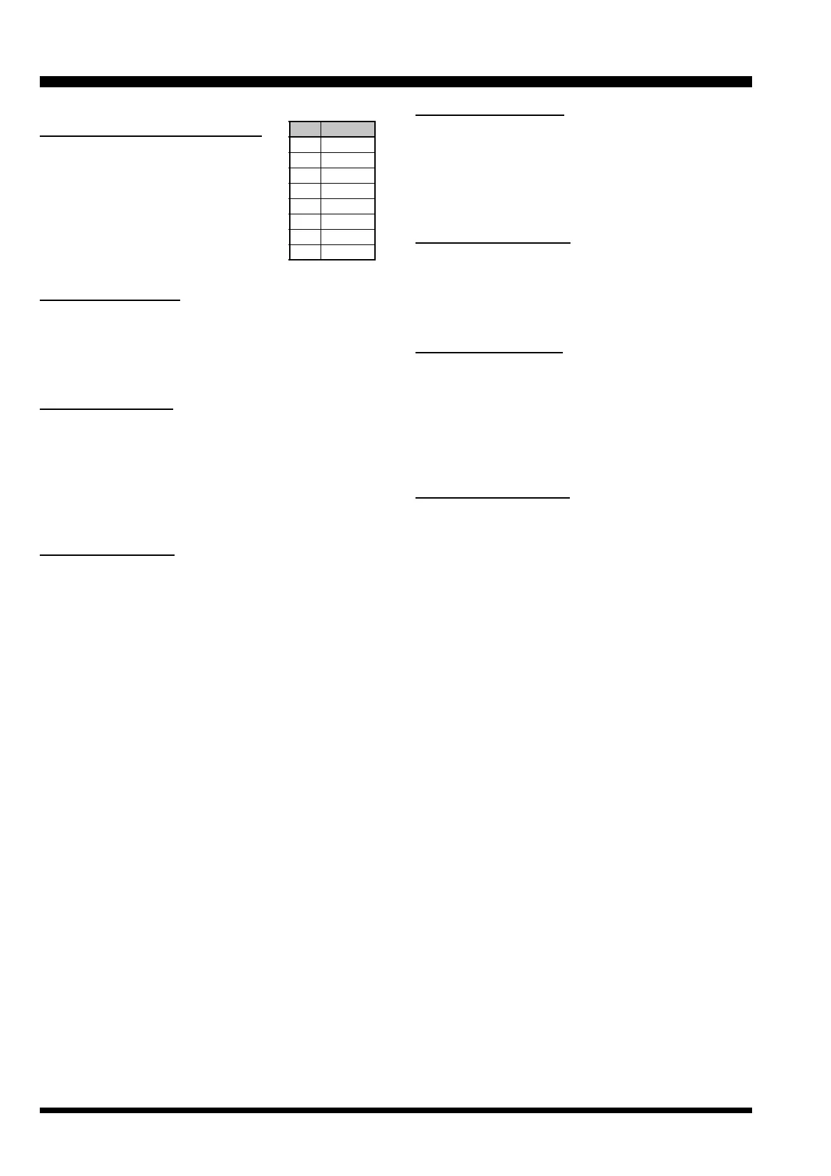
DB-25 CONNECTOR PORT
8
Pin I/O Port
10 7
13 8
15 5
16 4
17 3
18 2
19 1
21 6
 Loading...