DELTA 600
Battery charger / DC Power Supply
©2017 Vertiv Co. All rights reserved | DELTA 600 | 6012928 | Notice utilisation | v05 | 05.17
Adjusting the voltage U with the external potentiometer
The output voltage can be adjusted using the external potentiometer (use only the VERTIV potentiometer, code:
6002928). Connect the potentiometer as shown in the diagram. Set switches 2 and 3 to the "Us Manual" and
"External U" position. Setting range: see § Specifications.
Protections
The DELTA module is equipped with internal devices to protect both itself and the connected equipment:
• Polarity inversion protection (Caution, the rating of fuses FB and FU, indicated in the specifications
table, must be respected).
• Overload and output short-circuit protection by current limitation.
• Fire protection in case of internal failure by input fuse.
• Output overvoltage protection (Charger max.): protects the load in case of control loss by stopping the
module. Threshold set at the current voltage (floating or boost) + 10% of the rated voltage, and delayed
approximately 13 seconds (memorized fault).
• No current measurement protection: protects the battery in case of loss of limitation by stopping the
module, 10 s delay (memorized fault).
• End of battery discharge alarm (battery min.): Threshold set at 85% of the rated voltage, and delayed
2 seconds (fault not memorized).
These last faults are reported onto an NO + NC dry contact on terminals 1-2-3 of the connector, at rest in
default.
Note: To clear the memorized faults, power to the module must be turned off (mains and battery) for at least
30 seconds.
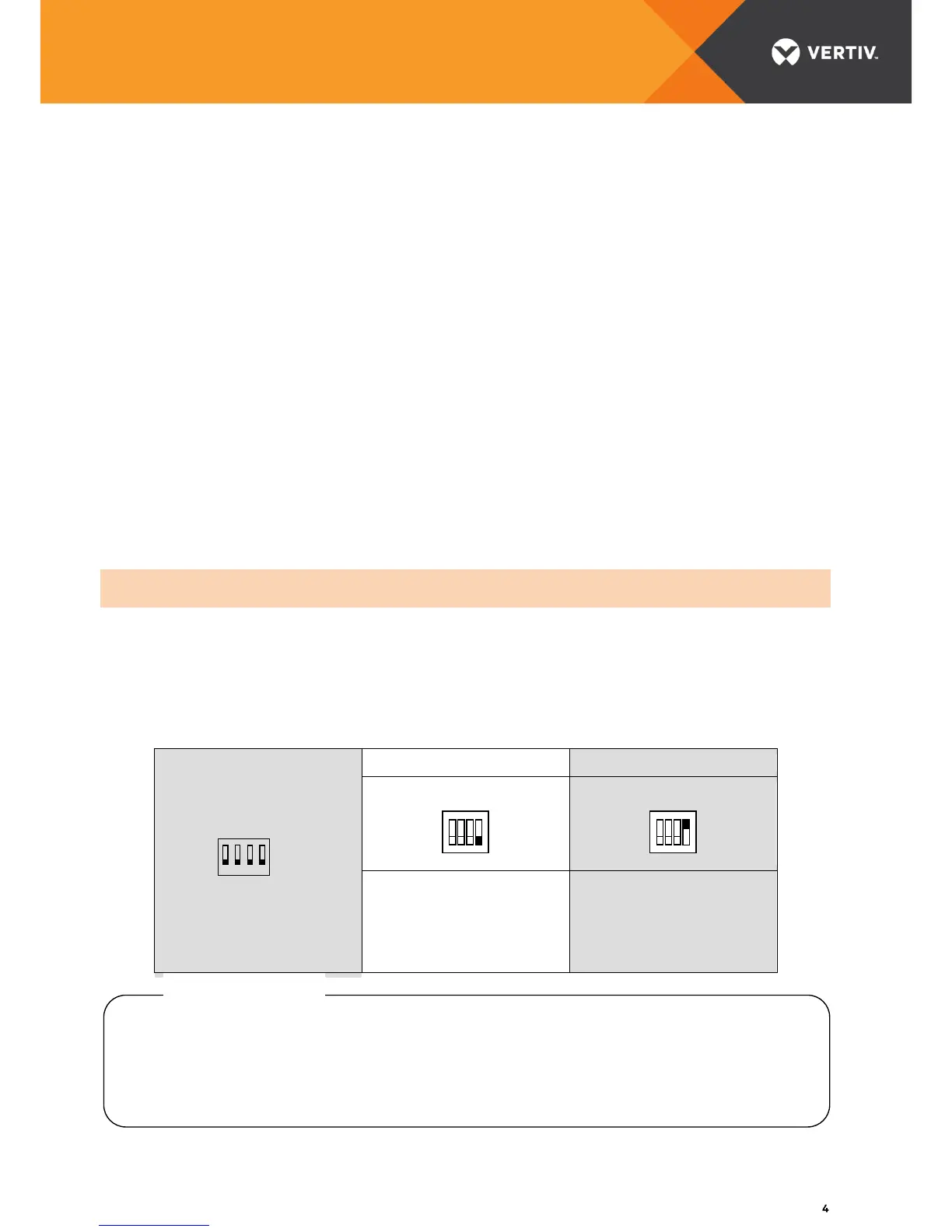
Fault report configuration:
The fault report may be configured in mM or D mode. The table below indicates the faults reported for each
mode.
The following is recommended to avoid signal disruption:
• do not use more than 2 meters of cable to connect auxiliaries,
• do not route auxiliary wiring outside the cabinet in which the DELTA charger is installed,
• route auxiliary wiring and power wiring separately,
• twist the auxiliary connecting wires serving the same function.
 Loading...