DELTA 600
Battery charger / DC Power Supply
©2017 Vertiv Co. All rights reserved | DELTA 600 | 6012928 | Notice utilisation | v05 | 05.17
5 TROUBLESHOOTING
Green mains presence
LED off and no output
voltage
Check that the power supply voltage is present on the charger
input and that the protection DjS is not open.
Green mains
presence LED
illuminated
Normal operation in floating mode.
Green mains presence
LED flashing
intermittently
Module in boost or battery test mode (see § Advanced
Functions).
If this is not the case, the module is in current limiting mode:
• The battery is highly discharged. It may take several
hours to recharge a battery.
• The module is in overload during use. If necessary,
disconnect the battery; check the output voltage and the
load.
Red fault LED
illuminated steady and
no output voltage
Check if the signal fault relay is reporting an anomaly. If so, the
module is faulty (overvoltage on output or no current
measurement). Turn DELTA charger power off (mains and
battery). Replace the module.
Battery discharged or defective. Recharge the battery for 24
hours, then perform a battery test (see § Advanced Functions). If
problem remains, replace the battery.
The output voltage is
not the desired voltage.
Check the reference of the equipment to ascertain the model.
Check the position of the mode programming switches (see §
Specifications).
If the problem remains, call VERTIV maintenance services at +33 472 47 63 80.
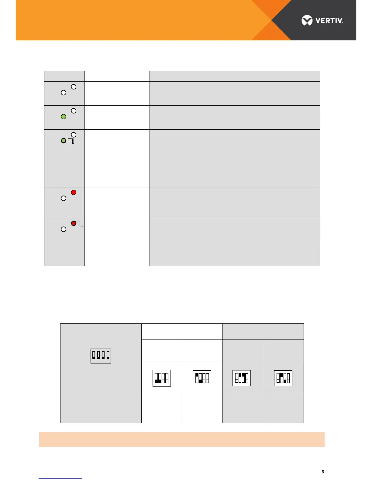
6 SPECIFICATIONS
Programming of the output voltage mode
Automatic setting:
"US Auto"
Manual setting:
"Us Manual"
Floating
potentiometer
"Internal U"
External
potentiometer:
"External U"
Note: The "Boost" potentiometer is used to vary the output voltage in boost mode, from the floating value to the
max. value (15 / 30 / 60 V)
 Loading...