REV : 0
REV DATE : 2/19
DPN004923
Page :1 /1
Form No.: DPN001040_REV4
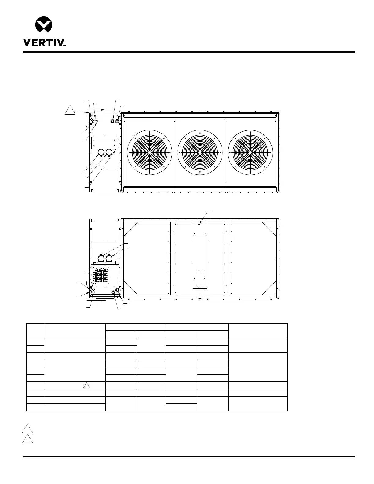
PRIMARY CONNECTION LOCATIONS
LIEBERT CW
X in. (mm) Y in. (mm) X in. (mm) Y in. (mm)
HV1 20-1/8 (513) 21-1/4 (540) 6 (153)
HV2 17-1/2 (444) 18-1/8 (460) 4-1/4 (109)
LV1 5-5/8 (144) 6-3/8 (163) 6-1/2 (166)
LV2 4-1/4 (109) 5 (129) 4-1/2 (115)
LV3 2-7/8 (75) 6-3/8 (163) 6-1/2 (166)
LV4 1-1/2 (40) 5 (129) 4-1/2 (115)
CD Condensate Drain N/A N/A 82-7/8 (2105) 55-1/2 (1410) 3/4" NPT Female
CP Condensate Pump 20 (509) 27-7/8 (707) N/A N/A 1/2" O.D. Cu
S Supply Pipe Connection 14-7/8 (378)
R Return Pipe Connection 8-7/8 (225)
POINT Description
Electrical Conn. (High Volt)
6-1/4 (160)
3-1/8 (79
Electrical Conn. (Low Volt)
Connection Size/Opening
2-1/2"
N/A N/A
1-1/2"
30 (762) 4-1/8" O.D. Cu
1-1/8 (29)
Notes:
1. Drawing not to scale. All dimensions from right corner on service side and have a tolerance of ± 1/2" (13mm).
2. Field pitch Condensate Drain line a minimum of 1/8" (3.2mm) per 12" (305mm). Install an external 5-1/2" (140mm) trap in the drain line (if desired).
The factory unit does not contain a trap. Select appropriate drain system materials. The drain must comply with all local codes.
3. Piping connection can be made at the top or bottom of the unit.
X
Y
O
O
X
Y
2
Data Hall Side
CW305, 375, 415 DATA HALL W/ HORIZONTAL DISCHARGE
FRONT RIGHT FACING ELECTRICAL/PIPING COMPARTMENT
Top View
Bottom View
HV1
HV2
LV1
LV3
LV2
1
LV4
CP
S
R
HV1
HV2
LV1
LV3
LV2
LV4
CD
Gallery Side
R
S
Data Hall Side