M
Morgan NewmanJul 27, 2025
What to do if the Protection Indicator (Yellow) is On for Vertiv Media Converter?
- DdillonfreemanJul 27, 2025
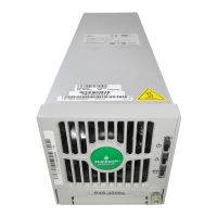
If the Protection Indicator (Yellow) is continuously lit on your Vertiv Media Converter, it could be due to several reasons: * DC input under or over voltage: Correct the DC input voltage to be within the acceptable range. * PFC over-voltage: Replace the converter. * Moderate load sharing imbalance: Check if the converter is properly seated in the module mounting assembly. If the problem persists, replace the converter. * Converter not fully inserted: Remove and properly re-insert the converter. * Converter over-temperature: Ensure the fan rotor isn't blocked, ventilation isn't obstructed, and the ambient temperature isn't too high. Relocate any nearby heat sources if necessary.