Last update: 2021/03/02 17:06 d2:laser_servo https://www.vescent.com/manuals/doku.php?id=d2:laser_servo
https://www.vescent.com/manuals/ Printed on 2021/04/17 23:32
The RAMP TTL is a trigger synchronous with the ramp. It is usually used to trigger an oscilloscope
while sweeping the SERVO OUTPUT. The RAMP TTL signal is also available on the back panel as a
dedicated trigger output.
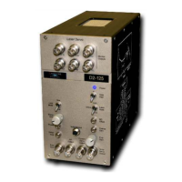
Front Panel
Power (LED indicator)
All electronic modules have a blue LED power indicator on the top right side of the front panel control
section. The LED requires +15V and -15V in order to light.
Lock Mode (two-position switch) -PL only
When set to the PEAK LOCK position, this switch routes the ERROR IN to a FM demodulation circuit
that extracts the error signal, which is then passed to the Loop Filter circuit. In the SIDE LOCK
position, the demodulation circuit is bypassed and the signal is fed directly to the Loop Filter circuit.
Additionally, the RF OUTPUT is disabled in SIDE LOCK.
Ramp Amp (1-turn knob)
The RAMP AMP sets the amplitude of the internal ramp generator.
Phase (25-turn trimpot) -PL only
When purchased as part of a complete laser system, the PHASE control is set at the factory and
generally will not require further adjustment. The PHASE control adjusts the phase between the dither
signal at RF OUTPUT and the local oscillator used to demodulate the signal coming in to ERROR INPUT.
It is used to maximize the demodulated DC ERROR signal while the laser is sweeping across the
desired transition(s) or lock points. The dither frequency is 4 MHz.
Dither Amp (25-turn trimpot) -PL only
The DITHER AMP control is used to set the amplitude of the dither signal at RF OUTPUT. When
purchased as part of a complete laser system, it is set at the factory and generally will not require
further adjustment. When used with the D2-105 Laser Controller, the RF OUTPUT should be connected
to the Laser Controller's RF INPUT to modulate the laser current. The DITHER AMP can range from 0 to
±75 mV (into a 1 MΩ load).
Error Input (BNC)
This is the input for the error signal. In SIDE LOCK mode, the signal is amplified by 26 dB and summed
with the DC OFFSET and DC OFFSET INPUT (back panel). In PEAK LOCK mode, the ERROR INPUT is
demodulated by the dither frequency and is then amplified by 26 dB and summed with the DC
OFFSET and DC OFFSET INPUT (back panel). In both modes the amplified signal can be seen with the
DC ERROR MONITOR and the AC ERROR MONITOR.
RF Output (BNC) -PL only
The RF OUTPUT signal is the 4 MHz dither or FM modulation signal. When used with the D2-105 Laser
Controller, it should be connected to the RF INPUT on the Laser Controller. In SIDE LOCK mode the
dither to the RF OUTPUT is turned off.


 To Next Page
 Loading...