Last update: 2021/12/17 00:00 d2:laser_controller https://www.vescent.com/manuals/doku.php?id=d2:laser_controller
https://www.vescent.com/manuals/ Printed on 2021/12/18 07:41
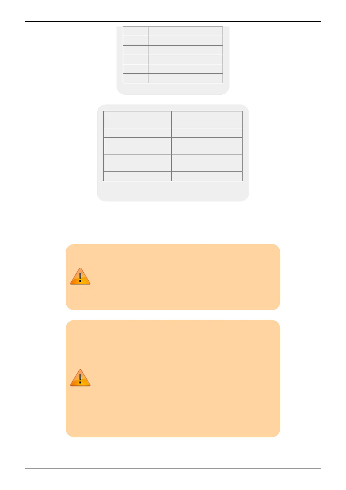
3 Rth1
4 Rth1-RTN
5 TEC2+
6 TEC2-
7 Rth2
8 Rth2-RTN
Tab. 1: TEC connector pin out
Connector Location
Connector (Hirose
Part Number)
D2-105 Bulkhead HR25-7TR-8SA
Cable Connection to
D2-105
HR25-7TP-8P
Cable Connection to
D2-100
HR25-7TP-8S
D2-100 Bulkhead HR25-7TR-8PA
Tab. 2: Connectors used in Temperature Control
Cabling
Back panel I/O
Power I/O (9-pin D-sub)
When making power connections to and from the D2-105,
always turn off the power supply, make connections to the
device, and then re-energize the power supply. Never
connect this device to a power supply that is switched on
and supplying power.
If you are considering using an Uninterruptible Power Supply
(UPS) to guarantee operation of your Vescent products
through a brown out or black out, great care should be taken
in choosing the model. Lower cost models tend to produce
modified square wave voltage profiles. The high-frequency
components of such a voltage profile may interact poorly
with the D2-005 (and down-stream active Vescent modules).
If you do choose to use a UPS, select a model that will
provide a sine wave voltage profile without higher harmonic
components to avoid potential damage to your high-value
equipment.
The power to each electronics module is through a 9-pin D-sub connecter through a power bridge