2021/12/18 07:41 15/19 Laser Controller
Product Manuals - https://www.vescent.com/manuals/
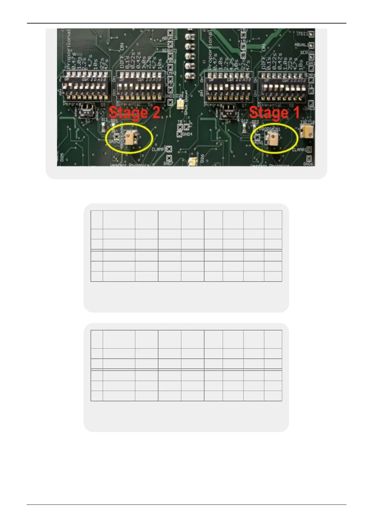
Fig. 5: Factory settings of T2 (left) and T1 (right) poles
T2
Prop.
On
0.47 s 1.0 s 2.2 s 4.7 s 10 s 22 s 47 s
On x
Off x x x x x x x
T2 Diff. On 0.1 s 0.22 s 0.47 s 1.0 s 2.2 s 4.7 s 10 s
On x x x
Off x x x x x
Tab. 6: Factory settings of T2 Proportional poles (first DIP
switch in figure) and T2 Differential poles (second DIP switch
in figure)
T1
Prop.
On
0.47 s 1.0 s 2.2 s 4.7 s 10 s 22 s 47 s
On x
Off x x x x x x x
T1 Diff. On 0.1 s 0.22 s 0.47 s 1.0 s 2.2 s 4.7 s 10 s
On x x x x
Off x x x x
Tab. 7: Factory settings of T1 Proportional poles (third DIP
switch in figure) and T1 Differential poles (fourth DIP switch
in figure)
To get good temperature stability, the temperature servo response needs to be tuned to match the
thermal load. Access to tuning the temperature response is provided on the right side panel of the
Laser Controller and requires removing that side panel to access the controls. The Laser Controller
provides two independent temperature controllers that are nominally identical. However, stage 2 has
front panel adjustment of the temperature set-point, while the stage 1 temperature set-point is a side-
panel adjustment. Additionally, the front panel TEMP SERVO INPUT adjusts the stage 2 set-point while