020815.11 13
vetus® Installation manual BPPPJA - BPPJA - Proportional panel for bow and stern thruster
+
–
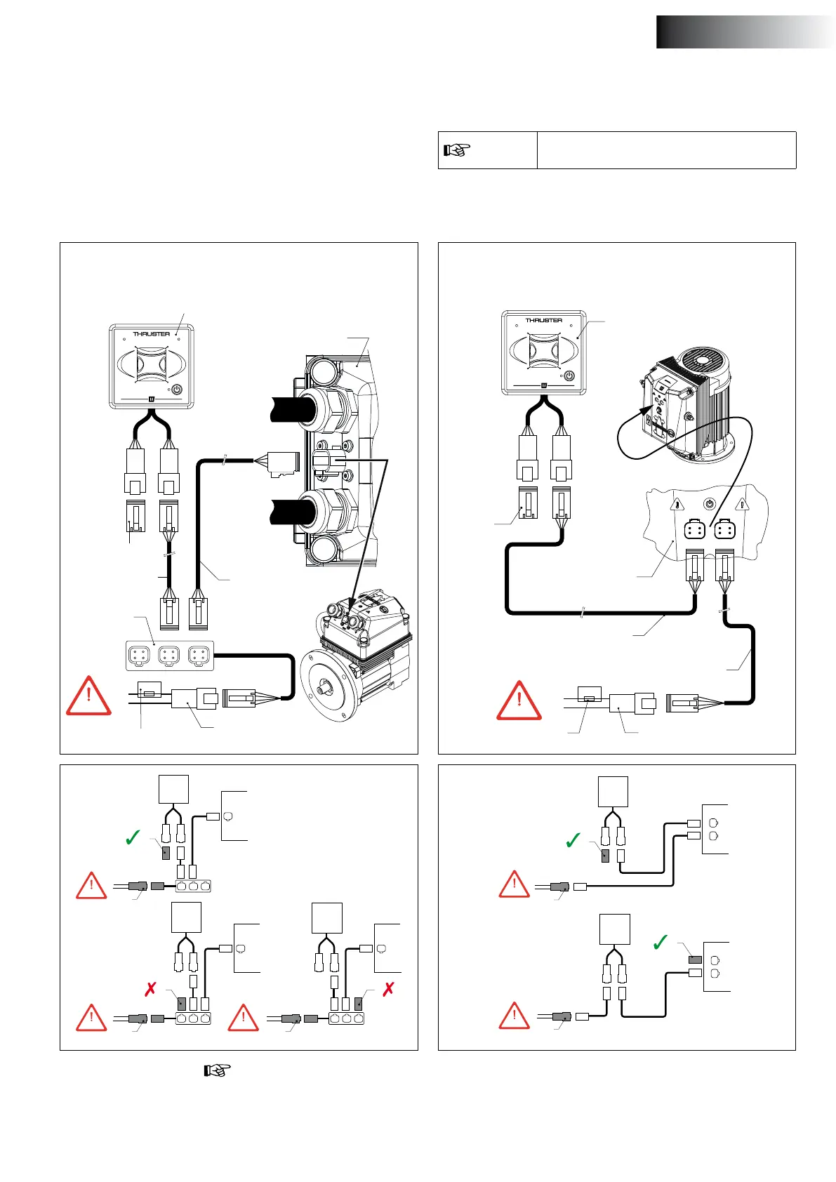
Control panel
Control voltage fuse
CAN-bus supply
Terminator
Connection box thruster
Connection cable
Connection cable
12 V
3 Installation
3.1 Connecting control voltage cables
• Mount the control panel at the helm position. There must be 150
mm of free space behind the panel.
• Make a hole of the correct size and t the panel. See principal di-
mensions page 72
• Connect the panel as shown in the diagram.
+
–
12 V
Control panel
Connection cable
Control voltage fuse
CAN-bus supply
Terminator
Hub
Connection box thruster
Connection cable
+
–
+
–
3
3
M
7
M
7
12 V
12 V
12 V
12 V 12 V
+
–
+
–
+
–
3
M
7
3
M
7
3
M
7
note
The CAN bus is a chain to which the bow thruster and the panels are
connected.
All types BOWPRO A,
except BOWA0571, BOWA0761
All types BOWPRO B
+ BOWA0571, BOWA0761
note
The CAN bus power supply must always be
connected to 12 Volt
Consult the relevant Bow and/or Stern Thruster installation manual
for the detailed CAN-BUS diagrams.
At one end of the chain, the power supply (3) must be connected
and the terminator (7) must be connected at the other end!
ENGLISH


 To Next Page