Do you have a question about the VEVOR AT1-2200X and is the answer not in the manual?
Key safety warnings regarding electrical shock and fire hazards.
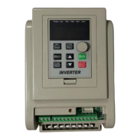
Identifies main circuit terminals and their functions for single-phase input.
Comprehensive list of inverter parameters, their specifications, ranges, and default values.
Details on password protection for settings and the countdown timer function.
Step-by-step guide on how to enter, modify, and save parameter settings.
The VEVOR AT1-2200X Inverter is a device designed to convert single-phase AC power into three-phase AC power, primarily for controlling the speed and operation of three-phase 220V AC motors. It offers a range of features for precise control and protection, making it suitable for various industrial and residential applications where motor speed control is required.
The inverter's primary function is to provide variable frequency drive (VFD) capabilities for three-phase motors. It takes a single-phase 220V AC input and outputs a three-phase 220V AC signal, allowing for adjustable motor speed and direction. The device supports multiple control sources for frequency and start/stop operations, including a panel keyboard, panel potentiometer, external analog signal, and RS485 communication. It also features multi-speed input frequency control, enabling predefined speed settings based on external switch inputs.
The inverter features a user-friendly operation panel with several keys for control and programming:
The inverter supports up to 7 section speeds, in addition to a main speed. These speeds are controlled by external input ports (X1, X2, X3) connected to COM. A '0' indicates the input port is connected to COM, while a '1' indicates it's disconnected. This allows for flexible, pre-programmed speed changes.
The inverter can be controlled via the panel keyboard, RS485, or external ports, offering versatility in integration with other systems.
Multiple stopping modes are available, including Inertial stop, Deceleration stop, Brake stop, and Emergency brake, providing options for different application requirements.
Separate parameters (P86-P91) are available for Jog Forward/Reverse frequency, rising/descent velocity, stopping modes, and braking time, allowing for precise momentary motor control.
The inverter provides clear fault codes on its display to assist in troubleshooting:
The inverter can be reset to its default parameters by setting P77 to 54321, which can be useful for troubleshooting or reconfiguring the device.
P08 is a hidden password that always displays 00000. To access and change P08 and other parameters, the correct hidden value of P08 must be entered into P09. This provides a layer of security against unauthorized parameter changes. The P09 value is nullified upon power cycle.
This feature allows users to set a countdown in hours. If P127 is set to a value less than 65535, the inverter will count down by 1 hour for every hour of operation. Once the countdown reaches 0, the frequency converter will stop, which can be used for scheduled maintenance or operational limits. If P127 is 65535, the countdown function is inactive.
The inverter includes parameters for main current overload (P78) and multiple section current overloads (P79-P84), allowing for fine-tuning of protection thresholds to safeguard the motor and inverter from excessive current draw.
This parameter allows setting the temperature at which the cooling fan starts running, ensuring optimal operating temperatures for the VFD.
The manual emphasizes critical safety warnings, including the high voltage nature of the device, the prohibition of disassembly, submersion, or parallel connection of transformers. It also stresses the importance of direct power supply connection to a GFCI wet location outlet, avoiding extension cords, and requiring installation by a qualified electrician in compliance with all applicable electrical codes. Any unauthorized changes or modifications to the unit will void the user's authority to operate the equipment.