This document describes the VEVOR Micro Inverter, a device designed for grid-connected solar energy systems. The inverter converts direct current (DC) from solar panels into alternating current (AC) for use in a household or to be fed into the electrical grid. The manual provides essential information for the safe installation, operation, and monitoring of the micro inverter.
Function Description
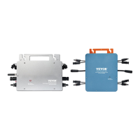
The VEVOR Micro Inverter is a crucial component in a solar power system, acting as the interface between solar photovoltaic (PV) modules and the electrical grid. Its primary function is to convert the DC power generated by individual solar panels into AC power that is compatible with the local electrical grid. This grid-connected design allows users to either consume the generated electricity directly or feed any surplus back into the grid, potentially reducing electricity bills or even earning credits. The micro inverter is designed for single-phase and three-phase parallel assembly, allowing for scalable solar installations. Models GT-600, GT-800, and GT-1200 are covered, indicating different power output capacities. The device incorporates various protection functions, including isolated island protection, voltage protection, frequency protection, temperature protection, and current protection, ensuring safe and reliable operation.
Usage Features
The VEVOR Micro Inverter offers several features to enhance its usability and integration into a solar power system:
- Scalable Installation: The inverter supports single-phase parallel assembly, allowing multiple units to be connected to a single branch circuit. For example, the GT-600 model allows up to 4 units per 230V grid branch, while the GT-800 allows up to 3 units. The GT-1200 supports 2 units on a 110V grid or 3 units on a 230V grid. This flexibility enables users to expand their solar array as needed.
- DC Input Compatibility: The micro inverter is designed to connect directly to PV modules. Users must ensure that the maximum DC input power of each inverter is not exceeded and that the open-circuit voltage (VOC) of the PV modules does not surpass the maximum DC input voltage of the micro inverter.
- AC Output Connection: The inverter connects to the AC grid, with specific models supporting AC110V or AC230V. Proper connection to the AC main cable and adherence to local grid standards are essential for safe and efficient operation.
- WIFI Cloud Monitoring: A key feature of the VEVOR Micro Inverter is its WIFI cloud monitoring capability. This allows users to remotely monitor the performance of their solar system using a smartphone or tablet application (such as "Smart Life").
- App Configuration: To set up monitoring, users need to install the micro inverter correctly and ensure it's generating power. Then, they download the "Smart Life" app, enable Bluetooth on their smart device, and connect to the same WIFI network as the micro inverter. The app guides users through registering an account, adding the inverter, entering home WIFI credentials, and confirming installation details.
- Real-time Data: Once configured, the app displays real-time data, including daily income, total income, total generated power, and total consumed power. It also shows sunshine duration and ambient temperature.
- Device Management: The app allows users to modify the device name, remove devices from their account, and share device monitoring access with others.
- Status Indicators: The inverter features LED indicators for WIFI status. A blue light flashing indicates it's waiting for configuration, while a blue light off signifies normal operation. A flashing blue light can also indicate network configuration issues or that the inverter has been deleted from the cloud. No light means WIFI cloud monitoring is working normally.
- System Control: The app interface provides control over the system switch, indicating successful connection and normal operation. The green light on the inverter signifies normal operation, with occasional flashing indicating MPPT (Maximum Power Point Tracking) for optimal voltage.
- Troubleshooting via App: The manual includes a comprehensive Q&A section for common issues encountered during app configuration and monitoring, such as the app not finding the inverter, changes in WIFI credentials, or the inverter appearing offline.
Maintenance Features
The VEVOR Micro Inverter is designed with safety and ease of maintenance in mind, though internal user-serviceable parts are not present.
- Safety First: The manual emphasizes critical safety warnings, including the risk of electrical shock. Users are instructed to always switch off AC power and disconnect the battery before performing any maintenance.
- Qualified Personnel: All maintenance should be performed by qualified personnel, as the product contains no internal user-serviceable parts. Removing the front panel or operating the product without all panels fitted is prohibited.
- Environmental Considerations: The inverter should not be used in environments where gas or dust explosions could occur. It must be installed in a heatproof environment, away from chemicals, plastic parts, curtains, or other textiles. Adequate free space for ventilation is crucial, and ventilation openings must not be blocked.
- Cable and Fuse Checks: Connection cables should be provided with fuses and circuit breakers. Users are warned never to replace a protective device with a component of a different type and to refer to the manual for correct parts.
- Storage and Transport: For storage or transport, the mains supply and battery leads must be disconnected. The product should be stored in a dry environment with a temperature range of -40°C to 65°C. Damage during transit is not covered if the equipment is not transported in its original packaging.
- Battery Information: Users are advised to refer to the battery manufacturer's manual for information on transport, storage, charging, recharging, and disposal of the battery, as the inverter operates in combination with a permanent energy source (battery).
- WEEE Compliance: The product is subject to European Directive 2012/19/EC, indicating that it requires separate refuse collection in the European Union and should not be discarded with normal domestic waste. It must be taken to a collection point for recycling electrical and electronic devices.
- Reset Functionality: In cases where the app cannot find the micro inverter or network issues arise, a red reset button can be pressed for more than 5 seconds to reset the device, allowing for reconfiguration.