EasyManua.ls Logo

VEVOR BHS223 - User Manual

VEVOR BHS223
40 pages
Print Icon
To Next Page IconTo Next Page
Loading...
Support and E-Warranty Certificate https://www.vevor.com/support
STEERING TROLLING MOTOR
USR MANUAL
MODEL:BHS223
We continue to be committed to provide you tools with competitive price.
"Save Half", "Half Price" or any other similar expressions used by us only represents an
estimate of savings you might benefit from buying certain tools with us compared to the major
top brands and doses not necessarily mean to cover all categories of tools offered by us. You
are kindly reminded to verify carefully when you are placing an order with us if you are
actually saving half in comparison with the top major brands.
Question and Answer IconNeed help?

Do you have a question about the VEVOR BHS223 and is the answer not in the manual?

Overview

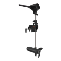
The VEVOR Steering Trolling Motor, model BHS223, is a robust and reliable electric trolling motor designed for various boating applications. It is engineered to provide efficient propulsion and precise control for a smooth fishing or boating experience.

Function Description

The VEVOR Steering Trolling Motor serves as a primary or auxiliary propulsion system for boats, offering quiet operation and precise maneuverability. It is particularly suited for trolling, allowing anglers to maintain specific speeds and directions with minimal disturbance to fish. The motor features a multi-position lever lock mounting bracket for secure attachment to the boat's transom, and an adjustable depth collar for optimal propeller submersion. Steering is managed via a tiller handle that controls both direction and speed (forward and reverse). The motor also includes a battery capacity indicator with 10 LED lights, providing real-time feedback on the remaining charge.

Important Technical Specifications

  • Model: BHS223
  • Maximum Current: 30A
  • No Load Speed: 1800 RPM
  • Maximum Thrust: 55 lb
  • Weight: Approximately 30 lbs (for the motor itself)
  • Recommended Battery: Deep cycle marine 12-volt battery with at least a 60-amp-hour rating.
  • Wire Extension Length (Recommended based on Max Amp Draw):
    • 30 lb thrust: 10AWG for 5-20 feet, 4AWG for 25 feet
    • 40 lb, 45 lb thrust: 10AWG for 5-10 feet, 8AWG for 15-20 feet, 4AWG for 25 feet
    • 50 lb, 55 lb thrust: 10AWG for 5 feet, 8AWG for 10 feet, 6AWG for 15 feet, 4AWG for 20 feet, 2AWG for 25 feet
    • 70 lb thrust: 10AWG for 5 feet, 8AWG for 10 feet, 6AWG for 15-20 feet, 2AWG for 25 feet
    • 80 lb thrust: 8AWG for 5-15 feet, 6AWG for 20-25 feet
    • 101 lb thrust: 8AWG for 5-25 feet
    • Engine Mount 160 (60 Amp@36VDC): 8AWG for 5-25 feet
    • 112 lb thrust: 8AWG for 5-25 feet
    • Engine Mount 160 (2x60 Amp@24VDC): 6AWG for 5-15 feet, 4AWG for 20 feet, 2AWG for 25 feet
    • E-Drive (50 Amp@48VDC): 10AWG for 5-25 feet
  • Operating Environment:
    • Ambient operating temperature range: -10°C to 50°C
    • Ambient operating humidity range: 5% to 95%
    • Maximum operating altitude: 10,000 feet

Usage Features

  1. Motor Installation:

    • Identify a clear transom area free from obstructions.
    • Open the transom clamp screws on the mounting bracket to fit over the top of the transom.
    • Position the lever lock mounting bracket on top of the transom.
    • Verify no obstacles interfere with the control box, handle, or prop.
    • Tighten the transom clamp screws by hand, avoiding over-tightening to prevent damage.
    • Adjust the tilt angle so the motor shaft is perpendicular to the water surface.
    • For transport, tilt the motor into the boat, with the motor and prop assembly completely out of the water, positioned close to the lever lock mounting bracket.
  2. Battery & Wiring Installation:

    • Follow Boat and Yacht Council (ABYC) standards for rigging.
    • Use appropriate circuit breakers and wire gauges based on the provided sizing table to prevent damage and ensure safety.
    • Connect to a deep cycle marine 12-volt battery (minimum 60-amp-hour).
    • Ensure proper polarity when connecting battery terminals: positive (+) to positive, negative (-) to negative. Never connect the motor directly to a starting battery.
    • For safety, do not switch the motor on until the propeller is in the water.
  3. Stowing the Motor:

    • When stowing or deploying, keep fingers clear of all hinge and pivot points and moving parts to prevent pinch injuries.
    • To stow, loosen the steering tension knob, slide the motor head up, grasp the shaft, and prevent it from sliding down. Adjust the mounting bracket and quick release tilt lever to position the motor away from the area that may cause injury.
  4. Adjusting the Depth:

    • Ensure the motor is submerged at least 12 inches to avoid churning or agitation of surface water.
    • Firmly grasp the composite shaft.
    • Loosen the steering tension knob and the adjustable depth collar until the shaft slides freely.
    • Raise or lower the motor to the desired depth.
    • Tighten the adjustable depth collar to secure the motor in place.
    • Always ensure the motor head is not creating a pinch point when adjusting depth.
  5. Adjusting the Steering:

    • Adjust the steering tension knob to provide enough tension for the motor to turn freely, yet remain in position without being held or tightened.
    • The tiller handle controls speed and direction (forward/reverse). Thrust decreases as you approach the OFF position from either direction.
    • Never turn the tiller handle to "OFF" if the handle is set or accidentally engaged or bumped, or if the prop will turn unexpectedly. This can cause injury or damage.
    • The Riptide Transom is not intended as a primary propulsion motor. Avoid heavy use that can cause elevated motor temperatures.
  6. Adjusting the Bracket:

    • The motor can be locked in a vertical position for shallow water or tilted completely out of the water.
    • Firmly grasp the control head or composite shaft.
    • Press the quick release tilt lever toward the shaft and hold to release the detent lock or T-bar to adjust the position of the mounting bracket.
    • Tilt to any of the positions on the lever lock mounting bracket.
    • Release the quick release tilt lever.
    • When adjusting, watch for pinch points on the lever lock mounting bracket and between the shaft and mounting bracket.
  7. LED Lights (Battery Capacity Indicator):

    • 10 LED lights provide an accurate display of the remaining battery charge.
    • 2-3 lights indicate a deep warning, suggesting approximately 10 minutes remaining (referring to a 24V 60AH battery).

Maintenance Features

  1. Propeller Replacement:

    • Tools Required: 1/2" open end wrench, flat blade screwdriver.
    • Disconnect the motor from all power sources.
    • Hold the propeller and loosen the prop nut with pliers or a wrench.
    • Remove the prop nut and prop washer.
    • If the prop does not readily slide off, take care not to bend the armature shaft while removing it.
    • Install the new propeller, prop nut, and prop washer.
    • Tighten the prop nut to 25-35 inch-lbs. Do not over-tighten.
  2. General Maintenance:

    • After every use: Rinse the motor with freshwater and wipe down with a damp cloth. Do not spray water into the ventilation openings in the head of the motor.
    • Composite Shaft: Requires periodic cleaning and lubrication for proper retraction and deployment. A coating of an aqueous based silicone spray will improve operation.
    • Propeller: Inspect and clean weeds and fishing line after every use. Fishing line and weeds can get behind the prop, damaging the seals and allowing water to enter the motor.
    • Prop Nut: Verify the prop nut is secure each time the motor is used.
    • Storage: To prevent accidental damage during transportation or storage, disconnect the battery whenever the motor is off the water. For prolonged storage, lightly coat all metal parts with an aqueous based silicone spray.
    • Battery: For maximum battery life, recharge the battery(s) as soon as possible after use. For maximum motor performance, restore the battery to full charge prior to use.
    • Battery Terminals: Clean with fine sandpaper or emery cloth (for flooded lead acid only).
    • Propeller Design: The propeller is designed to provide optimum operation with very high efficiency. To maintain this top performance, the leading edge of the blades must be kept smooth. If they are rough or nicked from use, restore to smooth by sanding with fine sandpaper.
  3. Troubleshooting:

    • Motor fails to run or lacks power: Check battery connections for proper polarity. Make sure terminals are clean and corrosion-free.
    • Motor loses power after a short running time: Check battery water level (add water if needed), and battery charge (restore to full charge).
    • Motor is difficult to steer: Loosen the steering tension knob on the bracket. Lubricate the composite shaft.
    • Experience prop vibration during normal operation: Remove and rotate the prop 180°. See removal instructions in the Propeller Replacement section.
  4. Environmental Compliance:

    • The product complies with WEEE Directive 2002/96/EC regarding waste electrical and electronic equipment. It must not be disposed of with other household refuse.
    • Batteries must not be disposed of in garbage bins. Comply with local town council regulations for proper disposal.
  5. FCC Compliance:

    • The device complies with Part 15 of the FCC rules, ensuring it does not cause harmful interference and accepts any interference received. Changes or modifications not expressly approved by MAKOSHARK could void the user's authority to operate this equipment.

VEVOR BHS223 Specifications

General IconGeneral
BrandVEVOR
ModelBHS223
CategoryEngine
LanguageEnglish

Related product manuals